Building an Operating Overhead Catenary System for “O” Gauge Model Railroads
Model Engines Under the Wire:
MTH 20-5601 New Haven E-33 Under Wire 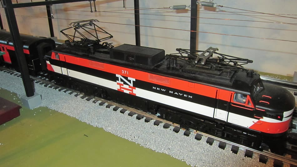
MTH New Haven EP-5 Under Wire 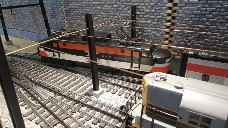
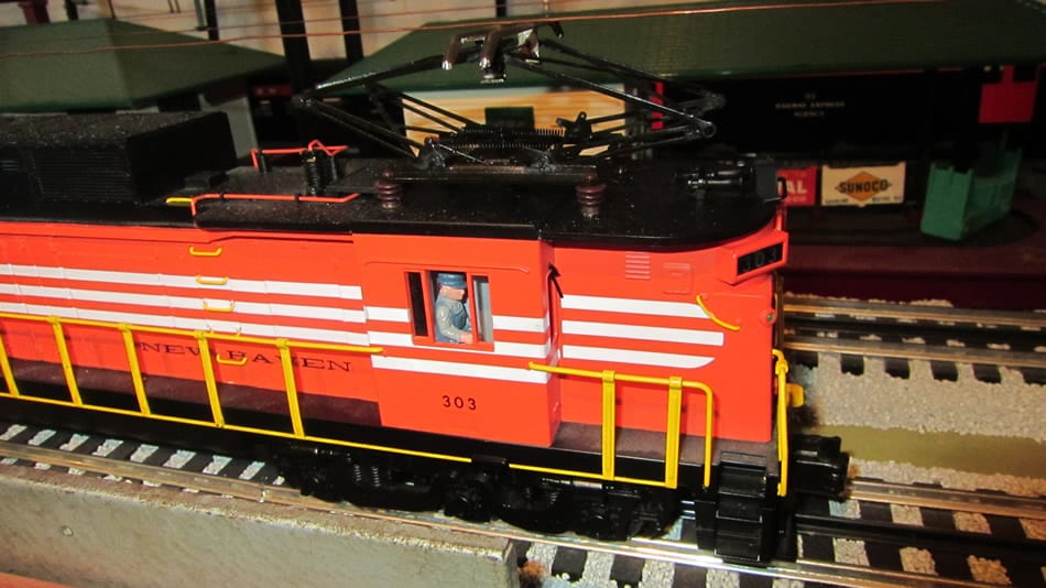
Lionel 3250 1950’s vintage EP-5 Under Wire in Terminal 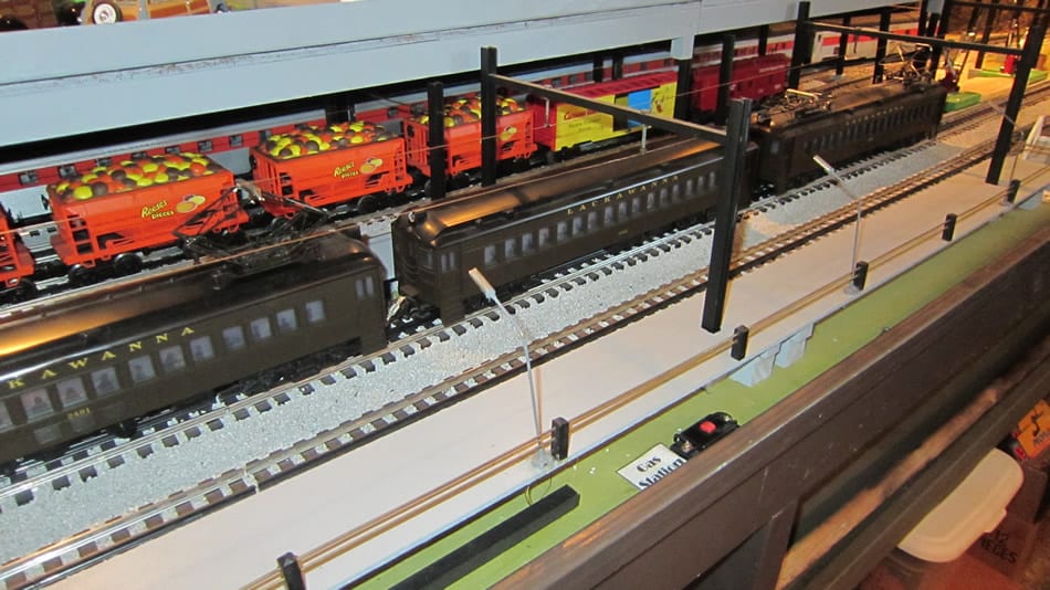
Lionel 1990’s vintage Lionel 6-18304/5 Lackawanna MU Cars Under Wire at Terminal
By Thomas P. Leyden TCA 69-2809/ TTOS 3479/LOTS 4618
www.bigredtrains.com Summer-Fall 2014
©Thomas P. Leyden 2014. Used by permission of author.
Foreword
For nearly seventy years I have had an avid interest in model trains. I was always particularly interested in the electric profile engines such as the Pennsylvania Railroad GG-1, the EP series of the New Haven and the Multiple Unit Cars (MU) of the DL&W (Lackawanna) Railroad. The latter took me to high school every day from Summit to South Orange, New Jersey. However, although Lionel made a non-scale version of the GG-1 in the late 40’s, no one made an affordable catenary system to go with it. Most of what was available was “over the top” expensive for a large layout.
As my layout developed to its current size (20 feet by 30 feet) and my craving for a working overhead catenary system took center stage I found the need to design, engineer and build my own semi-prototypical system. I had already built my first very rudimentary but working overhead catenary system in 1974.
When I retired in 1994 and began the design and construction of my new layout in a finished air conditioned attic, I had to take down the original system and decided to upgrade to the system described in this document. Not scale, but close enough.
The layout is big but I had time on my hands and a major league desire to “make it happen.” There was lots of trial and error involved. No one had a “how-to” book so I had to figure it out for myself. There were lots of trips to the hardware store to figure out what size spring to use to provide the necessary tension in the wires. Early on I decided to go with a single wire approach. Prototypical double wire with the ensuing soldering of endless “hangers” was more than I was interested in undertaking for my 450 linear foot right of way. After several not-so-pretty attempts at “hanging” the wire, I decided to go with what I call the “machine screw/tube” method where simple machine screws and small brass tubing (1/16”) are used. This allows the wire to be passed freely through the tube thereby allowing for a flawless tensioning of long runs of wire.
All in all it took nearly a year to build the infrastructure and hang the wire. At first, I had only my Lionel 3250 New Haven EP-5 to work with. I had already taken the third rail roller pickups off and rewired it for overhead power in 1974. Then the fun came. When I started it up for the first time the pantographs sparked like the real thing and the operation was practically flawless. After adjusting some of the “hangers” at switches because the pantographs would occasionally snag, the operation was declared a success.
Next came purchases of scale GG-1’s/Scale New Haven EP-5/New Haven E-33/New Haven EF3b/Lackawanna MU cars (just like I rode in in High School) /a second 3250 EP-5/Williams E-60/rewired Lionel 520. As the new engines were added I learned that each had their own arc as they swiped the wire. Minor adjustment of support locations had to be made to make use of the “learnings” obtained from watching the new engines do their individual “thing.” Now we have lots of fun and lots of sparks.
The toughest parts of the design/engineering were the crossovers and bridges. I’ve tried my best to describe the “how to” based on lots of trial and error and snagged pantographs.
For video highlights of the operating overhead catenary system, please visit my website: www.bigredtrains.com.
Bill of Materials
- 24 gauge bare copper wire (length to suit your needs). I got mine 40+ years ago from a wire customer I was calling on. I got 1000 feet at the time and probably have 200 feet left.
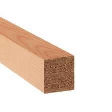
- 1″ x 1” x 8’ wood trim – available at lumber yard
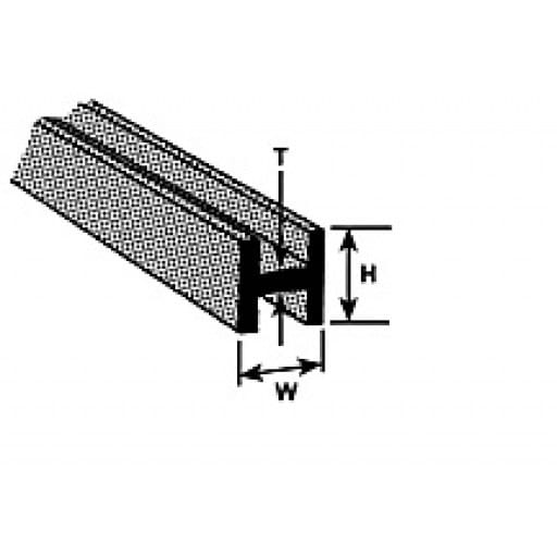
- Plastruct “H” columns (#H-12 [3/8”x 3/8”]) PLASTRUCT Scale Structural Shapes – 3-8″ H Column ABS (H-12:)
- ¼” x ¼” basswood sticks – available from National Balsa in various lengths http://www.nationalbalsa.com/default.asp
- 4-40 machine screws
- 4-40 hex nuts for machine screws (2 for each machine screw) — both screws and nuts are available from local hardware store
- Small Screws for mounting basswood sticks to “H” columns:
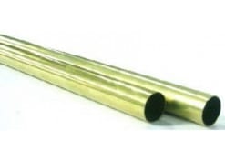
- 1/16” round copper tubing … tubing sized for wire used:
K&S 8125 Brass Tube, 1/16″ x 12″ (3-Pack) - brass rod – ????????
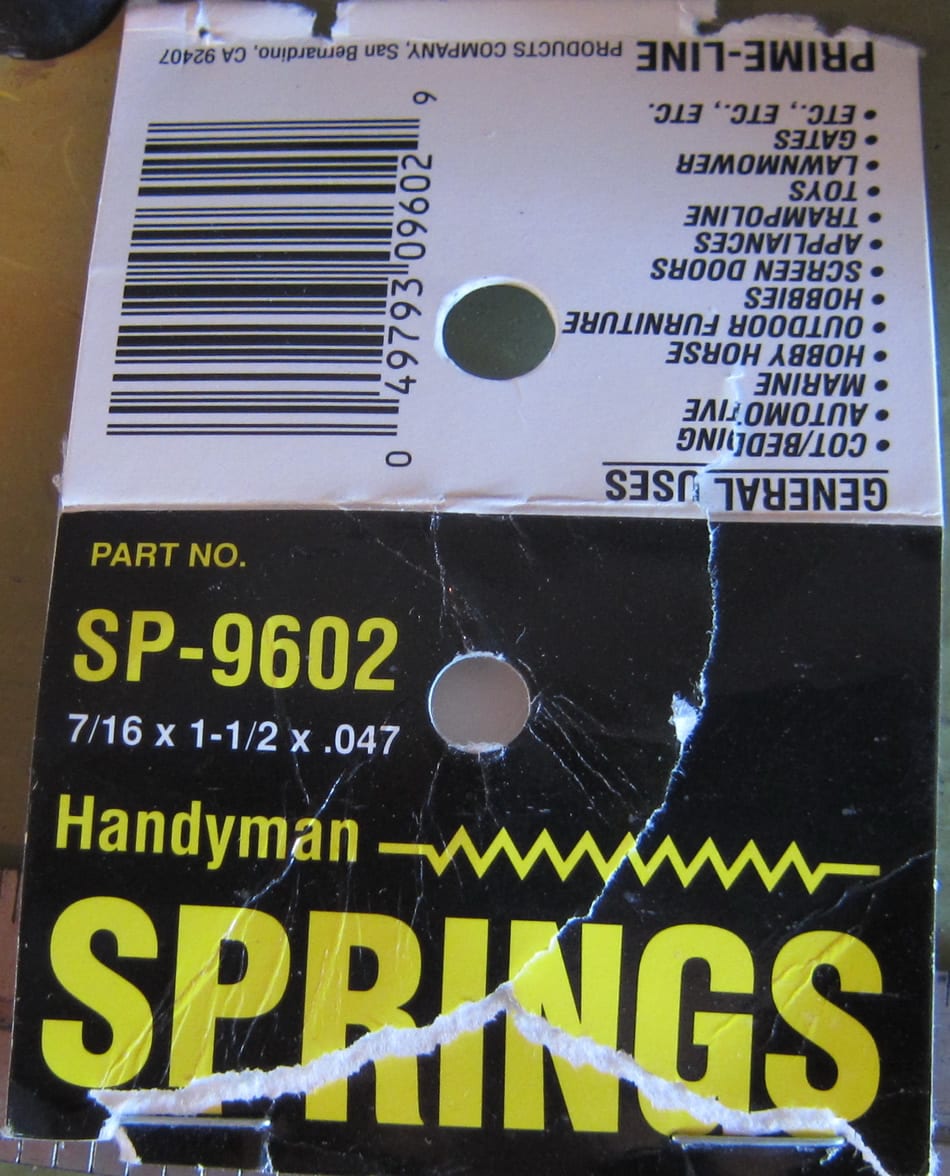
- Small springs to hold wire tension. [Handyman Springs Part # SP-9602 dimensions in photo]:
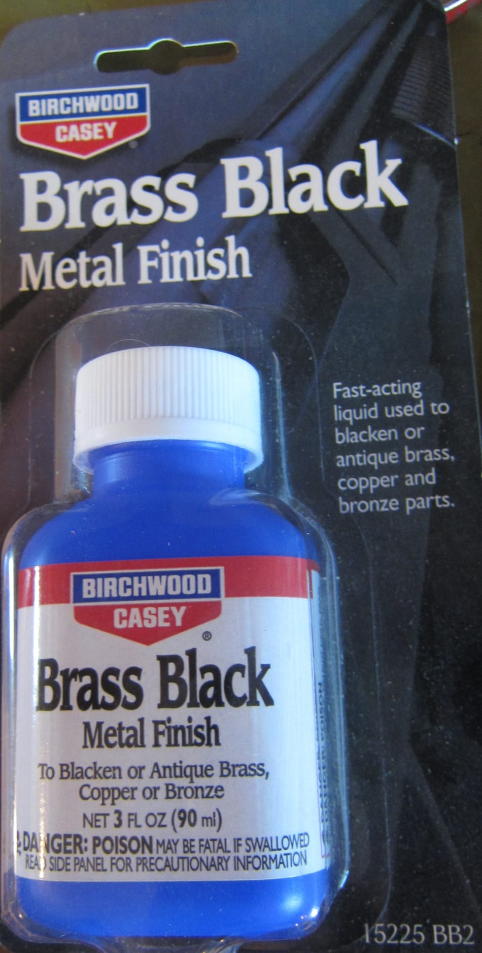
• Brass Black:
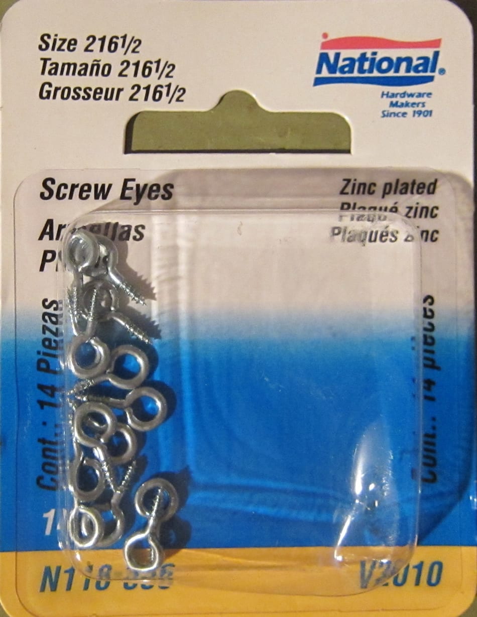
• Screw Eyes:
• Paint – Flat Black and Medium Grey
Building the Catenary System
Building the Catenary Bridge-Support Bases
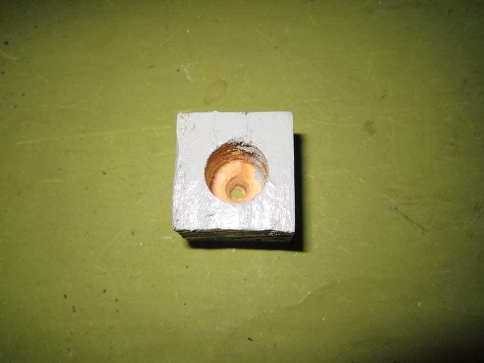
1. Cut 1″ x 1″ x 8′ wood trim into 3/4″ high pieces. Mark each with corner to corner “x” to indicate center of each piece. These will be catenary pole bases.
2. Use wood drill with sharp point and drill 1/2″ holes in center of 1″ x 1″ x 3/4″ pieces. DO NOT drill all the way through. Drill to leave 1/4″ wood at bottom with 1/8″ hole. This hole will be used to secure to tabletop.
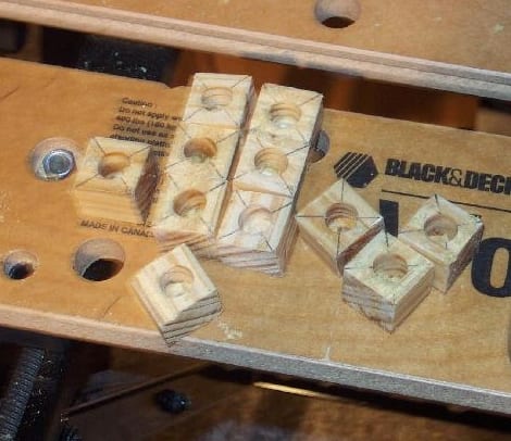
3. After drilling operation paint the bases a medium grey to simulate concrete.
Building the Catenary Bridge-Supports
(Note) I used a Dremel moto-tool with cutoff disc to saw (cut) “H” columns and basswood sticks
There are two kinds of Bridges; multiple track and single track.
1. Purchase the “H” columns from Plastruct (#H-12 3/8″ x 3/8″) Cut columns to 7 1/2″. This height can vary depending on your layout’s height limitations.
2. Purchase 1/4″ x 1/4″ basswood sticks. These sticks will be cut to suit specific need but I used 2 1/2″ for singles. You have to measure double or triple track span widths. Paint columns and basswood flat black.
3. Drill small holes in columns 1″ from top to accommodate tiny screws to mount single or multiple track crossbeams.
4. For single track and for most curves the crossbeams are cut to 2 ½” in length and mounted to the columns in the same fashion as detailed in 3. above. These crossbeams must be reinforced, either with ¼” x ¼” basswood sticks or with 1/8 rod as shown in the photo below to accommodate the upward force of the pantograph.
Assembling Catenary Bridge-Supports
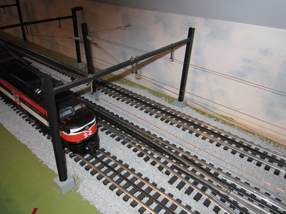
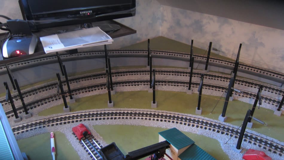
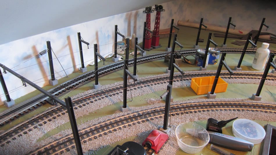
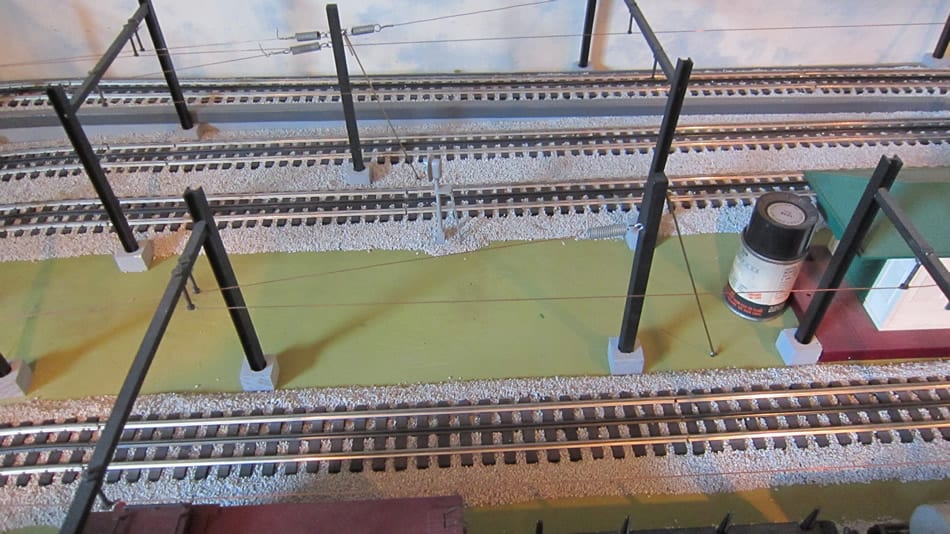
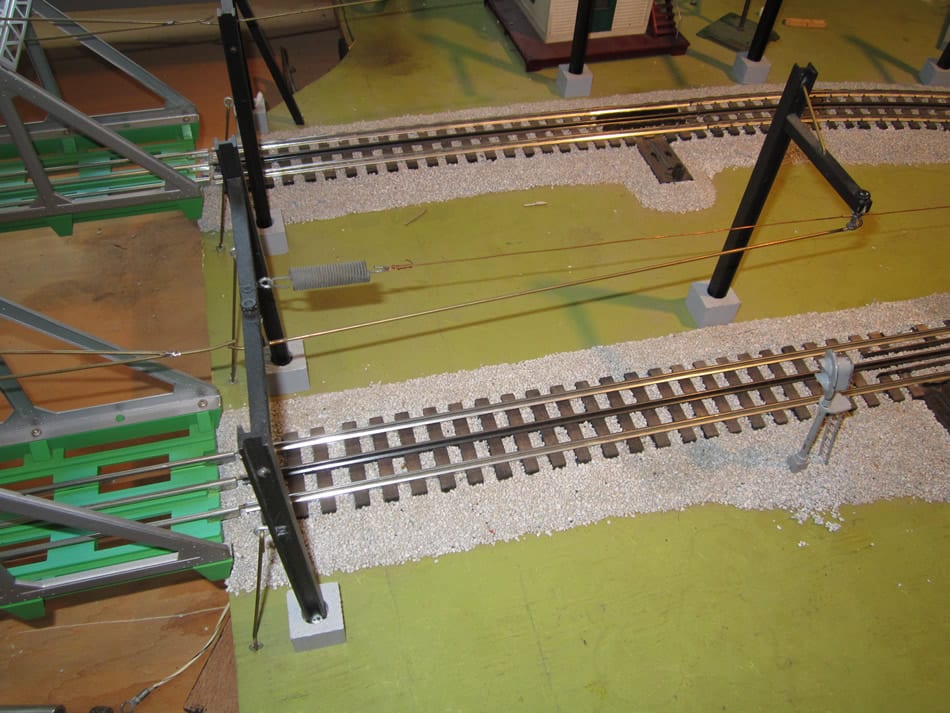
Measure and assemble catenary bridge-supports at predetermined places screwing bases to layout platform using appropriate wood screws. Straightaway bases were located 2 ¾” from track centers. Curve bases were located 2 ¾” to 3 1/2” from track centers. I built a template to insure uniformity.
a. Straightaways
Pick a location to start. I chose the beginning of a straightaway as a good place to start. I used a distance of 19” between the bases for straightaways. Other factors may necessitate shortening the distance, i.e. crossovers/switches.
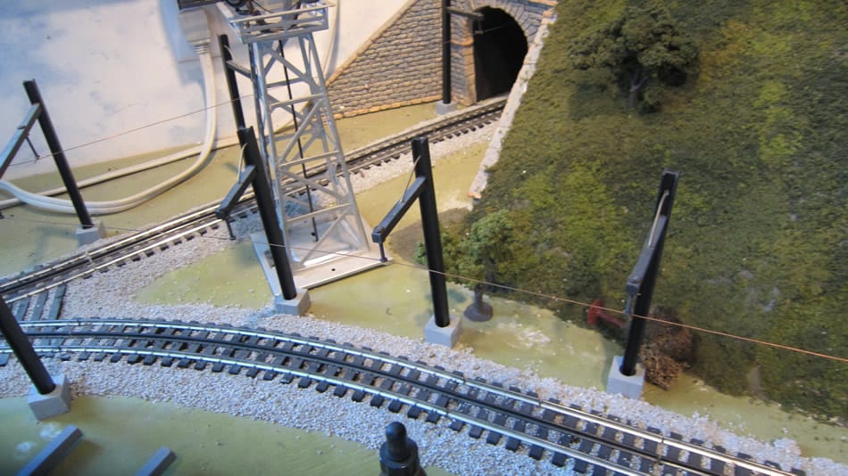
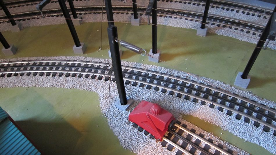
b. Curves
Trial and error is necessary to be sure curves are engineered appropriately. I placed poles a distance of 6” to 7” apart on curves depending on curve radius. (See photos below.)

Installing the Overhead Wire
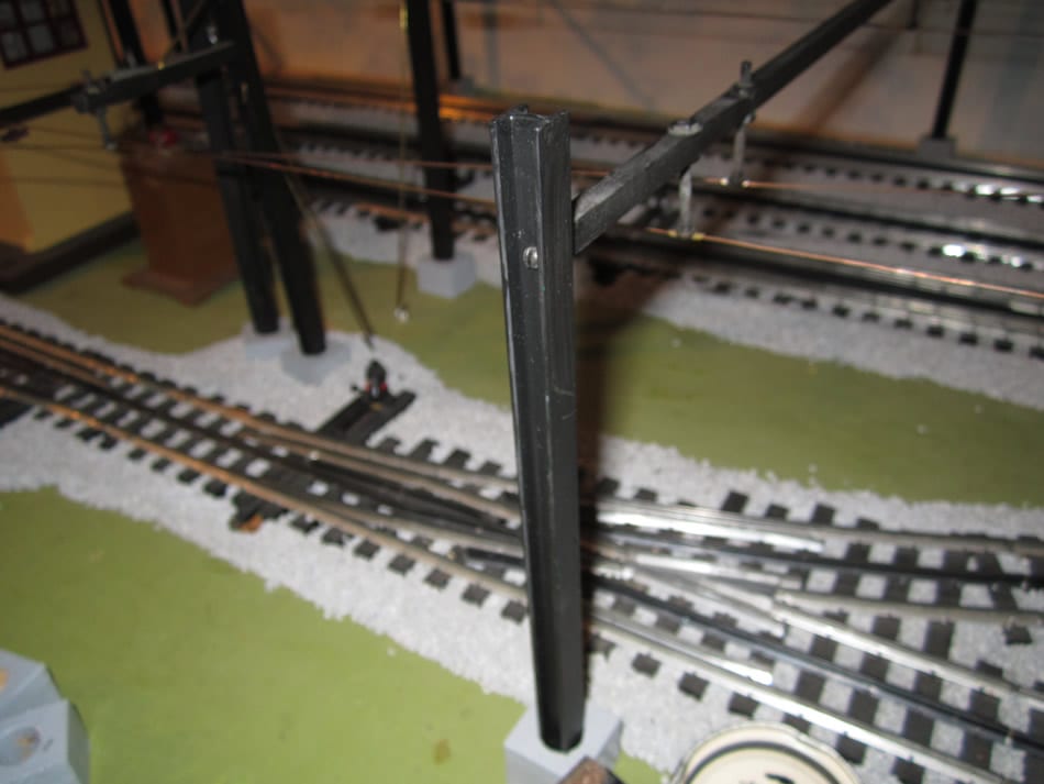
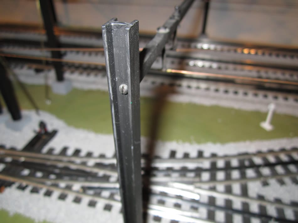
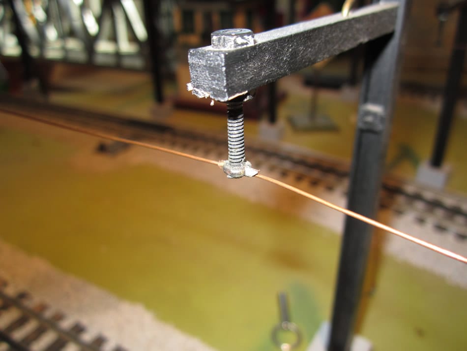
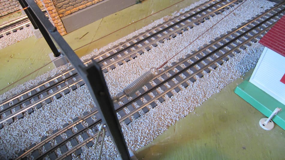
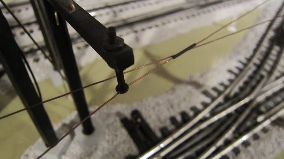
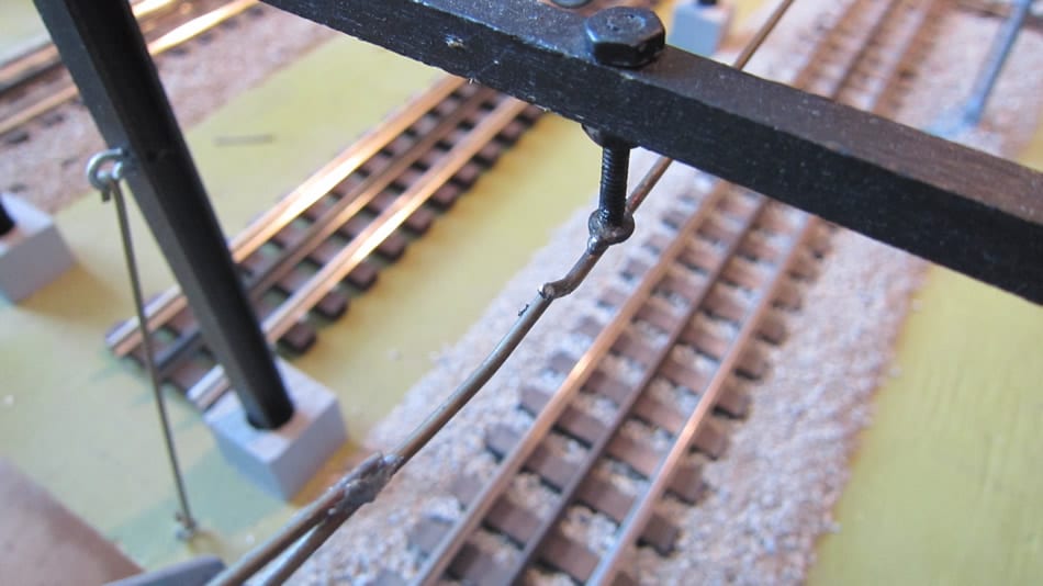
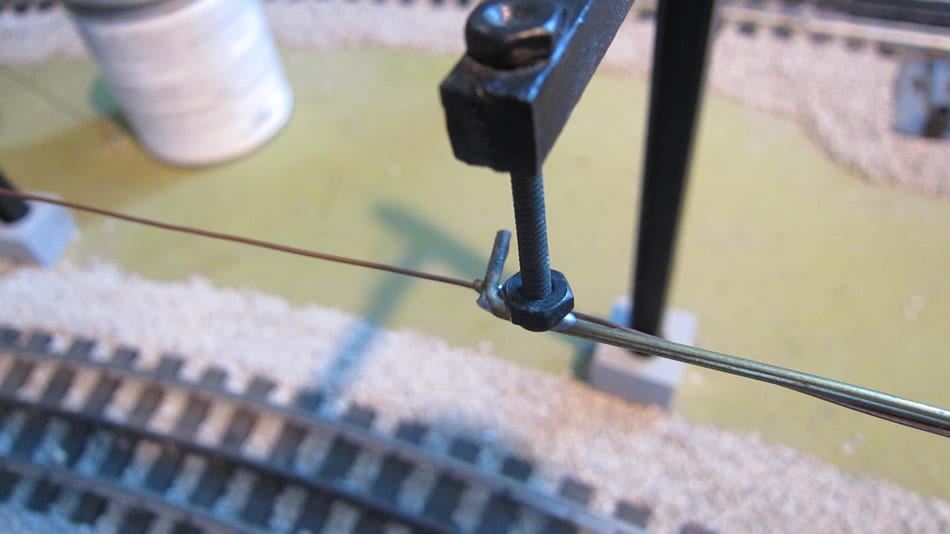
- “Blacken” the “shiny” machine screws and nuts with Brass Black product. I poured the Brass Black in a drinking cup and put the hardware (nuts/screws) in the cup a let them soak overnight. Then use a Dremel tool with cut-off wheel to widen the slot in the machine screw to accommodate tubing through which wire will be placed. Solder a small length of tubing in the widened slot (slightly larger than round head of machine screw). Cut the tubing at either side of machine screw at 45 degree angle to insure pantograph slides smoothly over tubing. This will result in what is referred to hereafter as a screw/tube “hanger.” See below:
2. Drill holes (1/8”) in basswood to accommodate machine screw/tube “hanger” location over the middle of the track. This location is particularly important on curves because the pantograph has its own arc around the curve … AND …each locomotive has its own arc … no two models are necessarily alike. Much trial and error is involved here. You can hand hold the catenary base and support to the tabletop and hand push the engine thru the curve to see where the pantograph will “wipe” the wire.
3. Fasten machine screw/tube “hangers” as shown in photos with hex nut on top and bottom of basswood stick to insure tightness. (See the photos above)
4. Pick “anchor points”…usually at the beginning and end of each straightaway…then thread wire through each screw/tube “hanger.” Curves should have their own “run” with “anchor points” at each end of the curve.
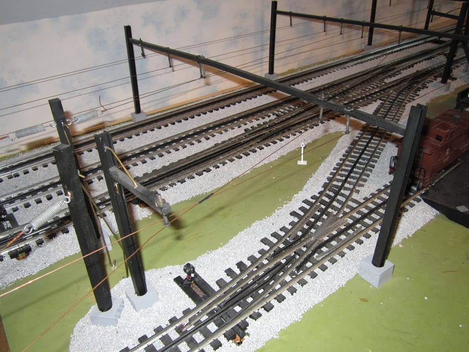
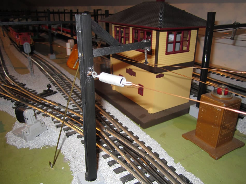
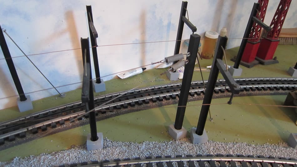
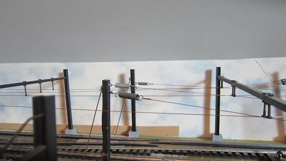
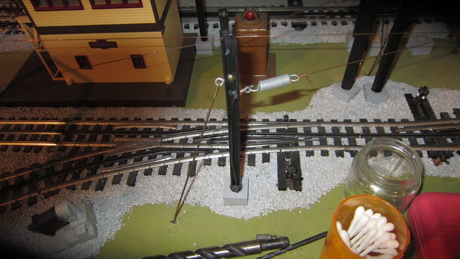
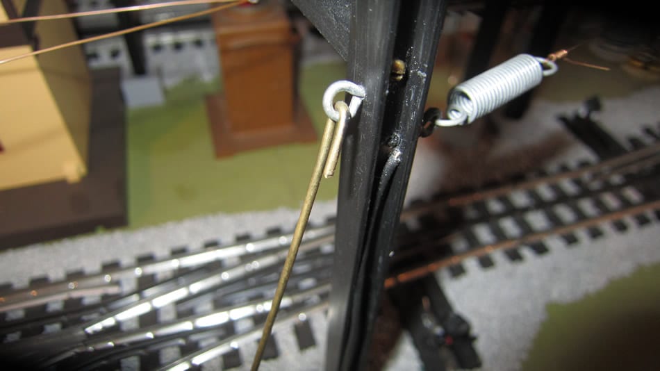
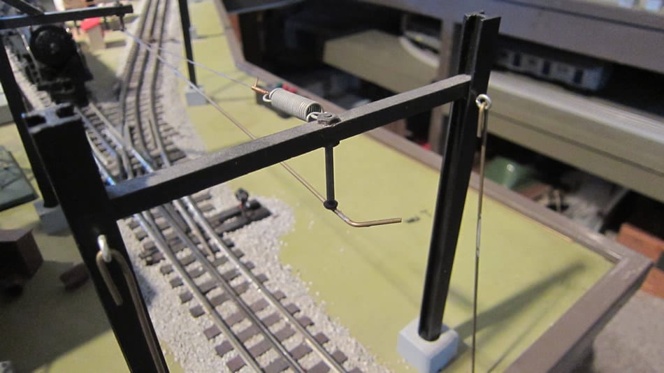
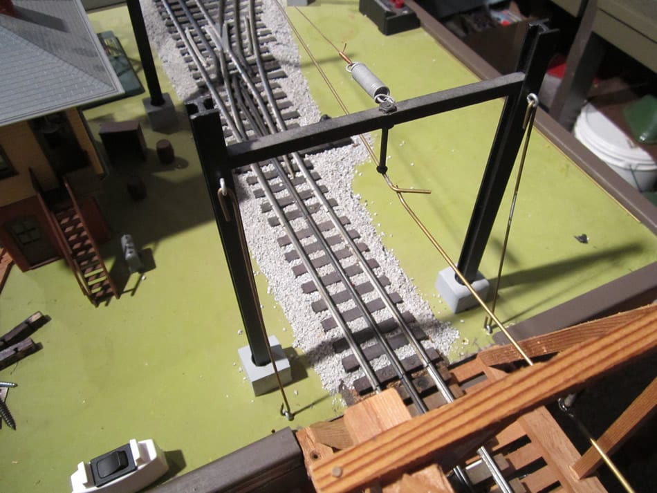
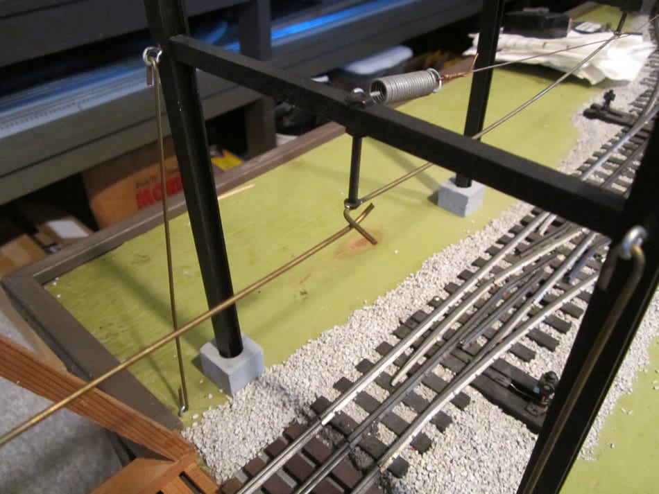
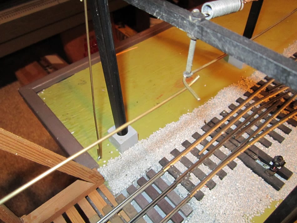
5. At each “anchor point” erect an anchor pole. For the most part I used ½” x ½” basswood cut to 7 ¼”, slightly shorter than catenary-bridge columns. (Plastic “H” columns tend to bend over time from tension) Screw eyes are inserted into the pole approximately 1” from the top. A screw eye is also attached to the tabletop 2 ½” from rear of pole. These two screw eyes are joined by brass rods bent over at each end. These supports will insure the poles can hold up under tension.
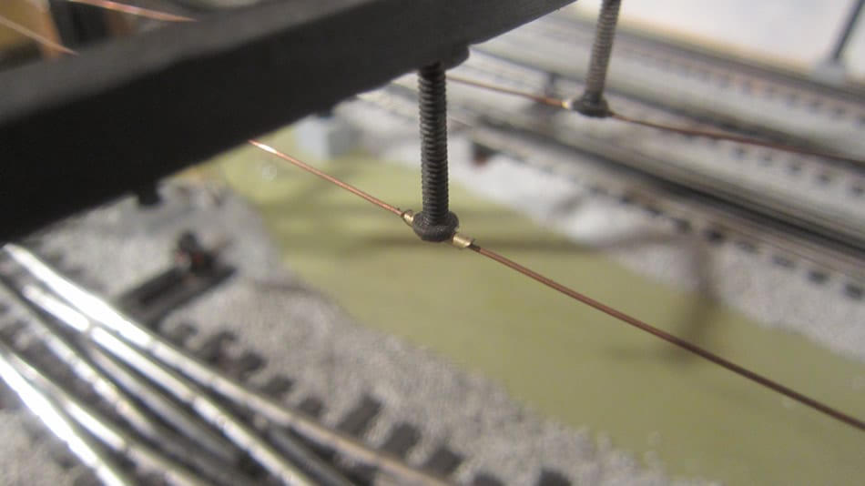
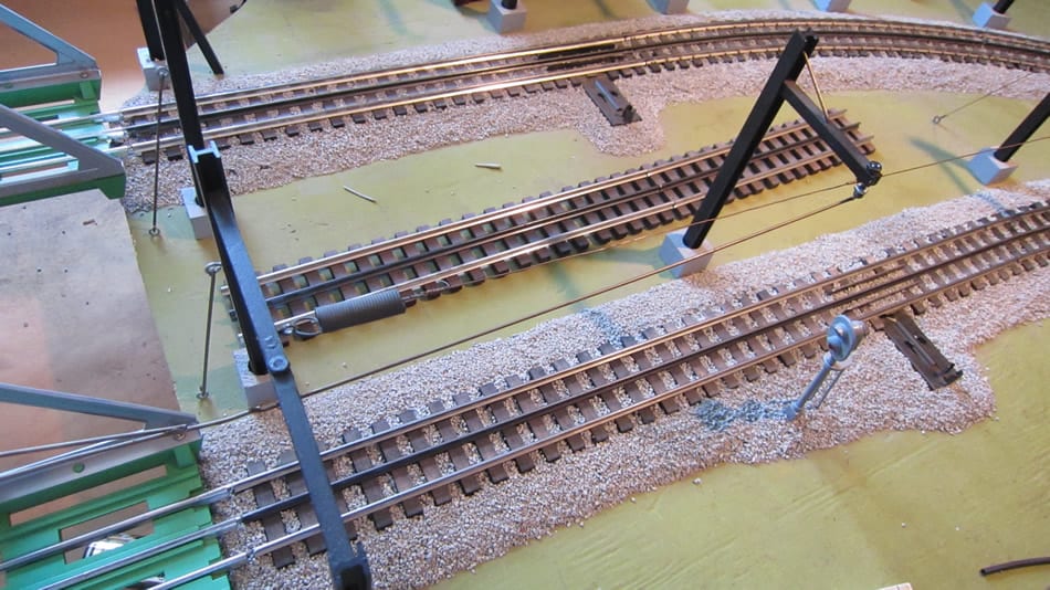
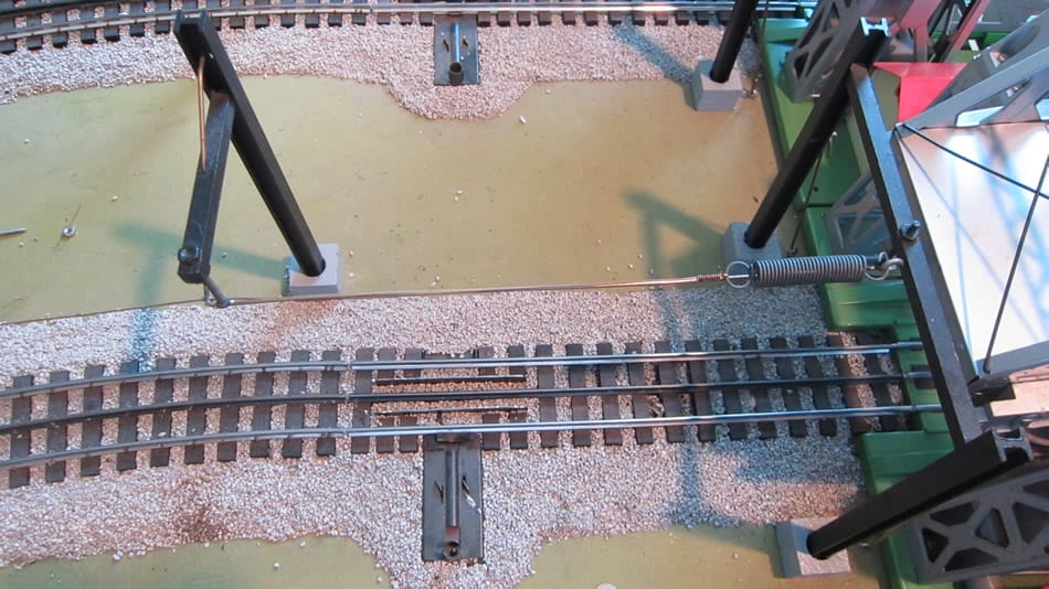
6. Insert a “screw eye” in the pole on the opposite (track) side of the pole approximately 1 ½” from the top and attach a spring to it. The catenary wire is attached at the other end of the spring by placing it through the spring end and wrapping the wire around itself as shown in the photos. Be sure the wire is tight and the spring under tension before finally wrapping the wire around itself….remember sagging in heat and tightening in cold just like real life. The following photos are intended to help the understanding of this important phase of construction. (See the five photos below)
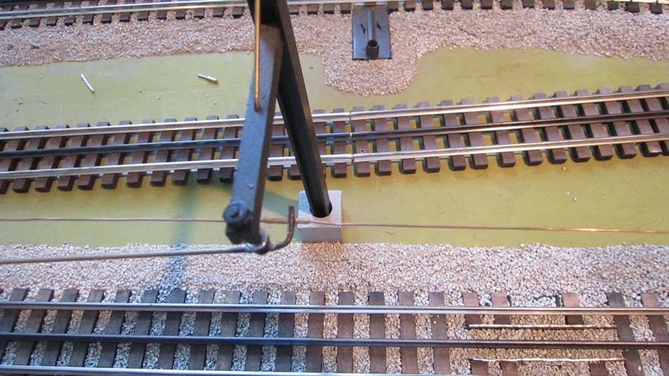
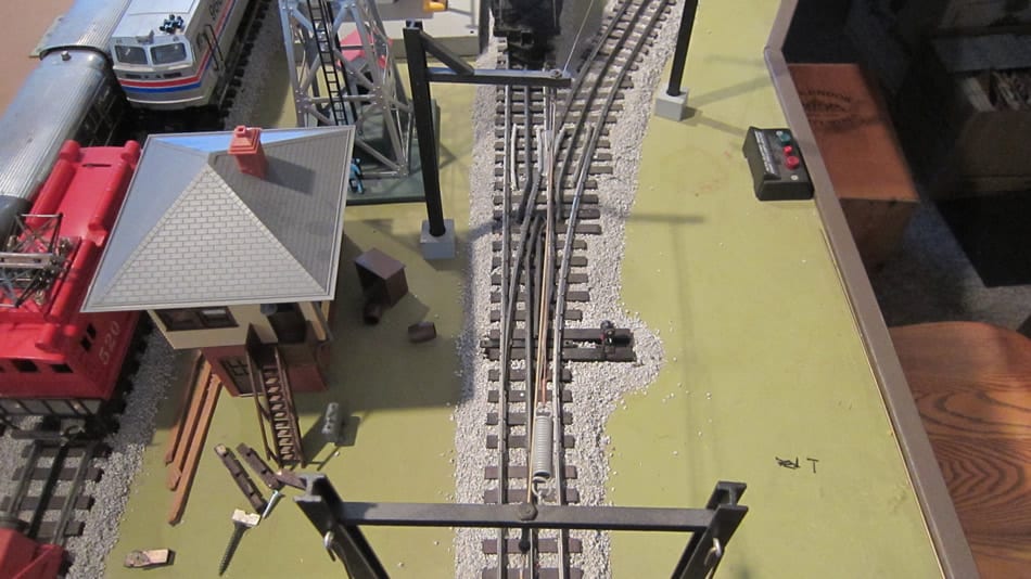
Installing Catenary over switches
Switches are the toughest part of the job. The subject is much too complicated for words so I have included photos at various switch locations so that you can see how I did it. There was lots and lots of trial and error….very difficult….but worth the trouble.
Getting power to the “system”
Every layout is different! Think ahead as to how many individually powered loops you wish to have. In my case I have five (5). Each of these powered loops has to be electrically insulated from the others. In most cases the insulator is “air.” Rarely, a short length of black wire insulation stripped from a length of 24 gauge hook-up wire is placed on the catenary wire and slid to a point where two wires might touch. (If this method is used be sure that the insulated wire is on top otherwise the pantograph might snag on it.)
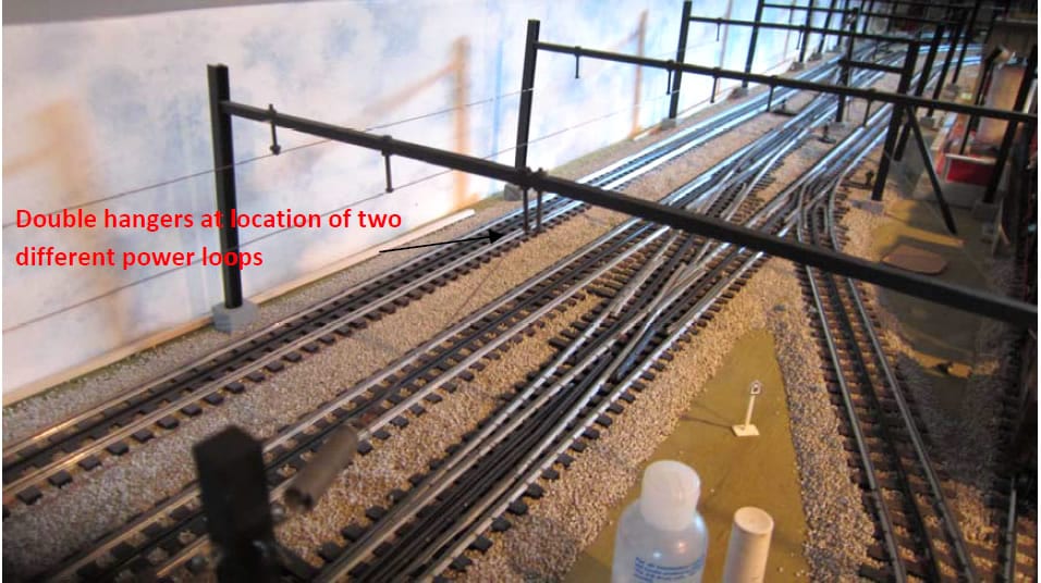
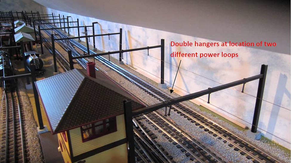
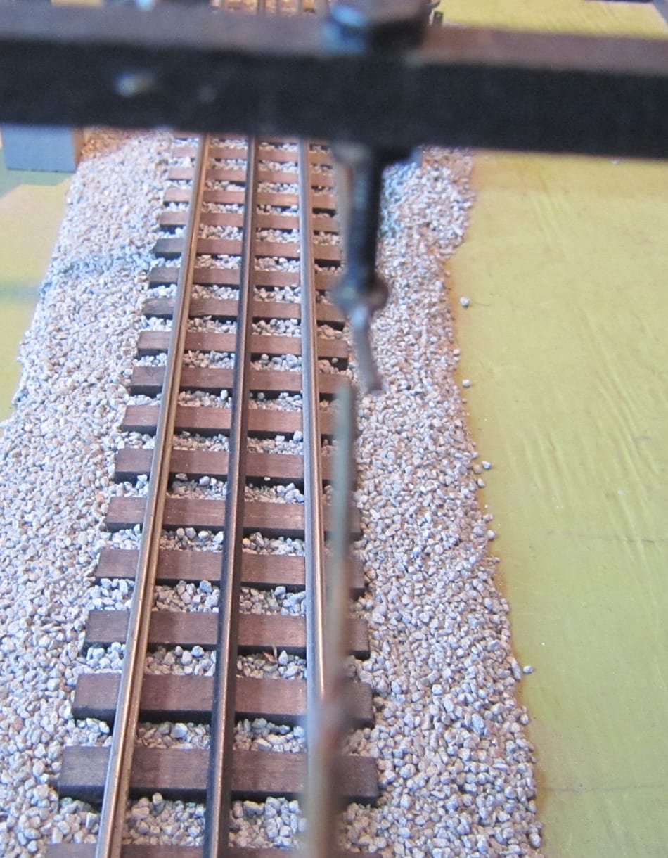
The separating point between power loops is usually at crossover or switching points. At these locations care must be taken to insure wires from the two loops do not touch each other. This will require two machine screw/tube “hangers” about ½ inch apart to carry the separate wires to the two loops of track. If properly measured and installed the pantograph will wipe both wires for a moment as it passes from one loop to another. The photos 20 and 22 show the double hangers in use.
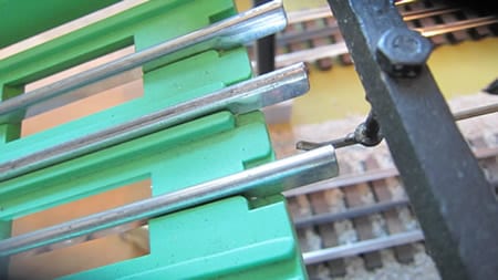
Getting power to the overhead wire is really simple. Drill an additional small hole (to accommodate wire) at the bottom of one of the “anchor point” bases. Feed the wire from your power source under the table and then up through the newly drilled “base hole” into one of the “H” column channels and attach the wire to the screw eye holding the spring which has the overhead wire in tension thereby making a circuit. One connection for each loop. No need to have “jumper” wires to distant points on the layout. My loop lengths are 100 feet. The photos that follow hopefully clarify the point.
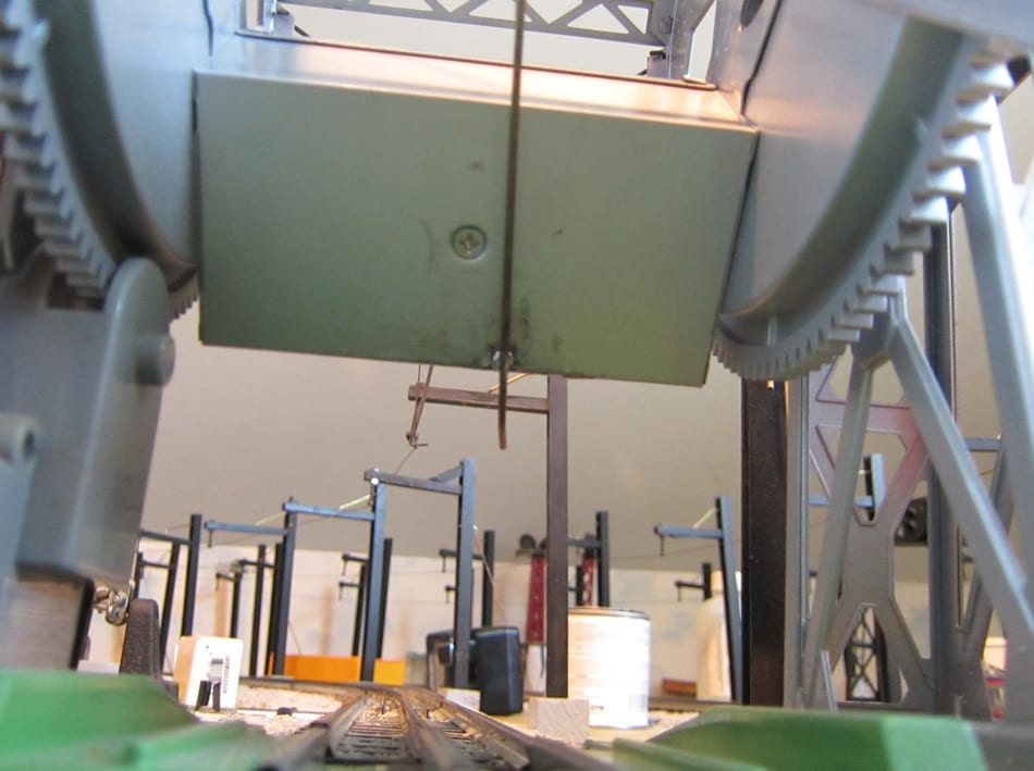
Installing Catenary on Moveable Bridges
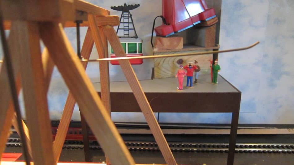
Installing catenary over moveable bridges on my layout such as the Lionel Bascule Bridge or a removable bridge was the biggest challenge in the construction of the catenary system. [I also installed the catenary in the Lionel Lift Bridge but that is much more complicated. I shall include that as an addendum when I take photos and write it up.] Basically I viewed actual bridges of all types on the nearby Metro North (ex New Haven) railroad to see how it’s done in real life. My system was patterned on what I saw.
Bascule Bridge
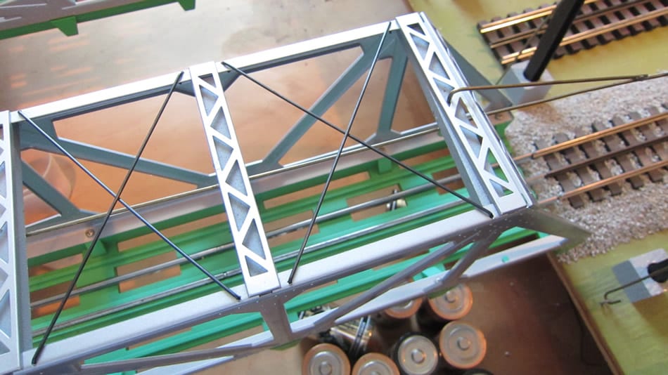
Since pictures speak louder than words I have included some photos below to help in the understanding. First, install catenary bridge-supports at either end of bridge. Approximately 10” from each of these are installed additional catenary bridge-supports. 1/8” brass rod is used to connect the two catenary bridge-supports and installed in such a way as to allow smooth transition from wire to the rod. I refer to these as “brass rod run-ups” or “run-ups.”
1/8” rod is affixed to ½” x ½” basswood sticks cut to fit in the trusswork on the top of the bridge. Each of these basswood sticks has a 7/16” machine screw inserted in predrilled 7/16” holes in the middle of the crossover span. Before installing in the bridge the rod is soldered to the machine screws at carefully measured locations to coincide with the location of the bridge truss spans, four in all. At this point the rod should extend well beyond either end of the bridge. It will be cut to proper length later. See captions under following photos for how to finish the “run-up” and on-bridge rod ends.
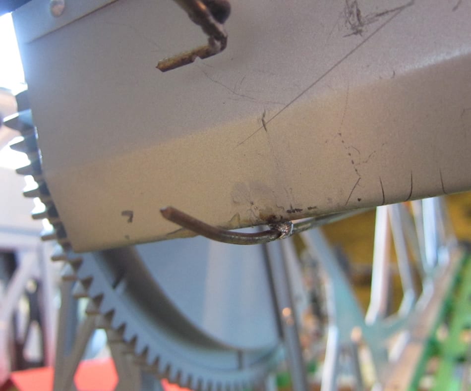
Removable Bridge
Similar to the Bascule Bridge setup “brass rod run-ups” are used at either end of bridge. Brass Rod is soldered to screw/tube “hangers” mounted under top. The rod is bent as shown in the photos to connect with the “run-ups” when the bridge is put in place on the layout.


