Small Can Be Better: Applying Modern Computer Technology to Layout Operations

By Russ Keil, TCA 04-56974Fall 2018
This describes how we are using small components of modern technology to improve exhibit operations at the National Toy Train Museum, and are extending such work to enhance TCA Atlantic Divison’s layouts.
It also demonstrates that just as we have choices ranging from large LGB trains to tiny Z scale, we have a growing number of options as to the size and characteristics of how we control them. Consider, for instance, how various layout controls that used to involve bulky rheostats, transformers and relays are now being manufactured in much smaller ways, and that toy train manufacturers are increasingly placing tiny computer components right on the trains to achieve new effects that gain interest.

Computer technology, increasingly miniaturized, is not just a smaller option, it provides ways to do more things with greater precision. It’s the type of thing that younger people are increasingly interested in, and provides a tool for better toy train operation, and attracting future members who are very much at home with computers, and enjoy their challenges.
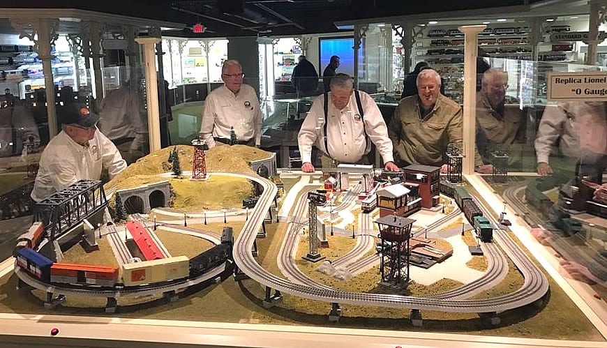
By way of example, TCA’s Atlantic Division has been increasingly successful with its portable layout, setting it up at venues where the non-train public can see it and hopefully get attracted to our hobby. It’s intentionally a fun display, with colorful amusement park elements that draw attention. The goal is to keep what visitors see simple, with the complexity that train collectors have to cope with out of sight. These efforts are paying off, with lots of people asking questions.
Behind the scenes, we’re using some nifty, small, technology that may challenge us, but will be right up the alley for the coming generation.
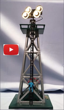
One example on our layout is Gabe the Lamplighter, and a tiny microcomputer.
Gabe is a relatively dumb accessory initially made by America Flyer in the 1950’s, and reproduced by Lionel and MTH in the more recent past. It’s a tower with lights on the top, a ladder for Gabe to climb and a control box with 2 switches and knob to turn on the spotlights manually.
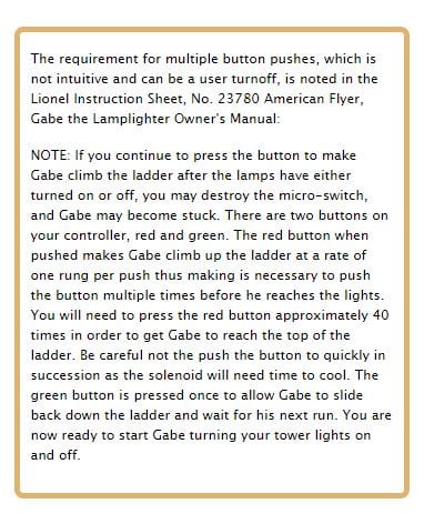
In original form, the user had to press a button approximately 40 times to make Gabe climb the ladder a single rung at time. Then they could turn the lights on or off using the light knob. To make Gabe descend the ladder, one pressed the descend button, which dropped Gabe from top to bottom in free-fall. Not wanting little children to think they could free-fall down a ladder safely, I wrote the code so Gabe would descend the ladder one rung at a time. How was this done?
INTRODUCING ARDUINO
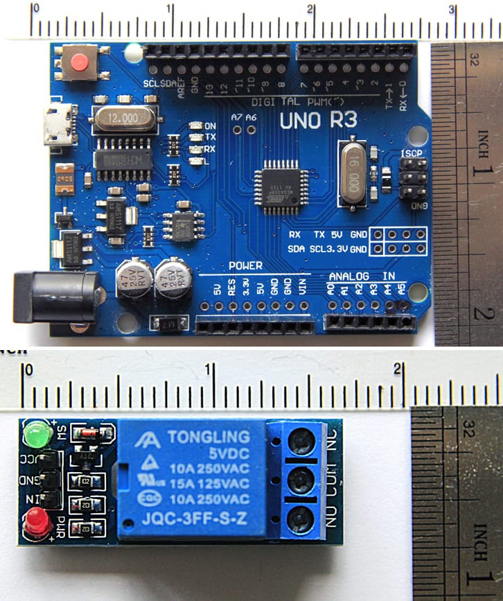
First, we purchased an Arduino Uno R3 microprocessor board with a micro USB (right top), which is smaller than a pack of playing cards, and cost less than $4.00, and also several small relays (right bottom).
What is Arduino? It can be described as an open source computer hardware and software environment, with a user community that designs and manufactures single-board microcontrollers and kits for building digital devices that can sense and control objects in the physical and digital world.
Arduino products are distributed as open-source hardware and software, which are licensed under the GNU Public Licensing, permitting the manufacture of Arduino boards and software distribution by anyone. Arduino boards are available commercially in preassembled form, or as do-it-yourself kits. They can be purchased directly from the Arduino site, or from other places, sometimes modified. More about that later.
On the Atlantic Division layout, I removed the original control box and replaced it with an Arduino and 3 relays which control the lights, the climbing up and climbing down the ladder. When activated by one push of a button, the spotlights flash several times to draw the user’s attention to the accessory. Gabe then climbs one step at a time, reaching the top, the lights are turned on, and he then climbs down the ladder one step at a time. At the bottom, Gabe rests for a few seconds, climbs the ladder again, turns off the lights and climbs down. The lights flash several times before the accessory goes to sleep waiting for another button push. Kind of basic, but the kids love it!

The division layout has several other Arduinos (all the Uno R3) for making the crossbucks flash, controlling timing for the power to all of the amusement park rides, operating the hot air balloon ride, and controlling the air whistle. The schematic above was generated by software available free on the Fritzing site.
Arduinos are great for sensing something like a button push or an infrared beam break, and then triggering something to happen like a gate going down. The functionality of many such uses may be very simplistic, but can produce quite effective results.
ANOTHER EXAMPLE OF APPLYING AUDUINO AND SOLVING PROBLEMS
Since the Arduinos have been highly effective on the Division’s layout, we decided to install some at the National Toy Train Museum. Power to all five tracks on the D-265 Department Store Layout that was added this year, is controlled by a single Arduino and five pushbuttons. A second Arduino controls the Train Orders building.
Are these control foolproof? Do the use “artificial intelligence”? Will we be free of challenges for humans to resolve? No, not at all. (Well, not so far anyway!) For instance, we were having a problem with the first track on the D-265 layout since it has a hill. If the train timed out on the uphill portion of the track, when it started up again, it was drawing a lot of current and cooking the coil in the 5VDC relays. After some pondering, we decided to use the 5V relays to switch a 30 Amp 12V relay to power the track. That stopped the relays from burning up. We saw similar problems when trains derailed and shorted the track.
The last remaining issue is still with track 1 and the hill. Unless we run a newer engine with speed control, the trains will either stall on the uphill or derail on the downhill depending upon the voltage settings. To fix this, we are planning to use a current sensor to measure the current draw when the train is on a level surface and during the climb. Then when the current sensor measures a decrease in current demand (downhill), I can reduce the voltage to a digital dimmer to prevent the train from derailing. Once back on the level surface, the voltage will be ramped up again.
To assure that I know the train is on the flat track I’m changing the logic for track 1 so that after the timer expires, the train will not stop until it breaks an Infrared beam which will be placed on the flat portion of the track. The beam-break detector consist of two components: an IR Emitter (LED) and an IR Receiver (pictures on last page). An extra lead on the Receiver is connected to one of the Arduino input pins that will give me a 0 when the beam is broken and a 1 when it is seeing the emitter. These are the same parts we will be using on the Standard Gauge layout ($1.95 a pair).
Indeed, shortly, the Standard Gauge layout at the Museum will get its first Arduino to control the crossing gates, semaphores and dwarf signals. This installation will include infrared beam-break detectors (see example on next page) that will determine the direction of the trains and drop or raise the crossing gates sequentially as well as control the other trackside devices.
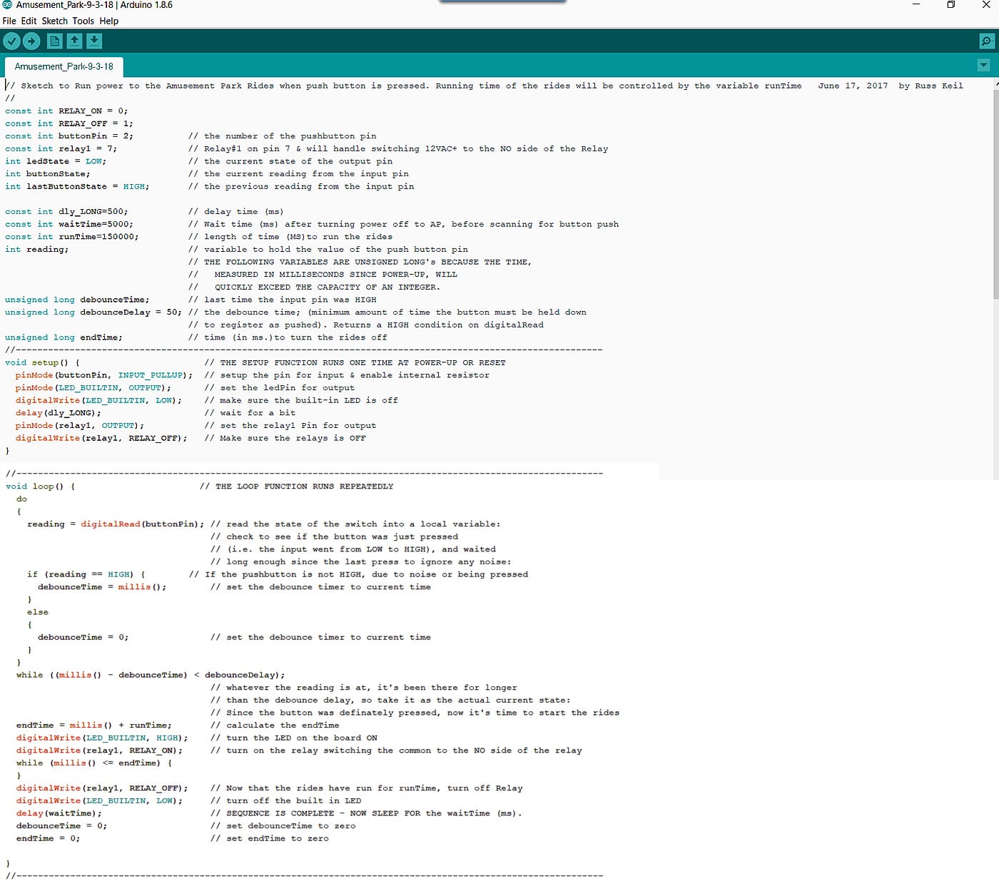
— The Arduino IDE (Integrated Development Environment) seen above is free. —
Yes, the Arduino has to be programmed! But don’t let it scare you!
While I have a background in this field, people can learn how to do it if they apply themselves, making use of a downloadable process, or doing it online. It takes some time, focus and thought, but the results are worth it! (Or get a helpful high-school student to lend a hand!) These devices are capable of performing chores that formerly required much larger and less flexible controls.
Arduino is being used around the world: At universities it is widely adopted in the fields of engineering, the Internet of Things, and robotics, to name just a few. In teaching, it’s finding use in high schools and up. For playing, primary schools use toys powered by Arduino technology to introduce physical learning, logic, building skills, and problem solving.
It blows the mind! For a thoroughly mind-expanding introduction, see Massimo Banzi, one of Arduino’s innovators, in this video:
A visit to the Arduino website at https://www.arduino.cc/ will be an eye-opener. If you’re interested, spend some time there soaking up the information. They also have a number of tutorials here. Give some thought to how you might play with this technology and learn your way into its use. Give some thought to reaching out to students who very likely will know more about that than you do, but could be exposed to an aspect of toy trains that they’ll appreciate!
As if that’s not enough change to cope with, there are other miniaturized, more complex computers about the same size that can do many functions that your desktop computer can, even running Windows 10! Take a look at the Raspberry Pi miniaturized computer that kids around the world are also using. Most likely more power in a tiny package than you’ll need! https://www.raspberrypi.org/
Challenging? Yes!
The way of the future? Quite likely!
Something for train collectors to consider? You bet!
For those interested in considering further technical aspects of this effort, we present additional information below. Learning such things takes time and effort. If you have questions, feel free to contact me.
First, a quick overview of some standard Arduino components:
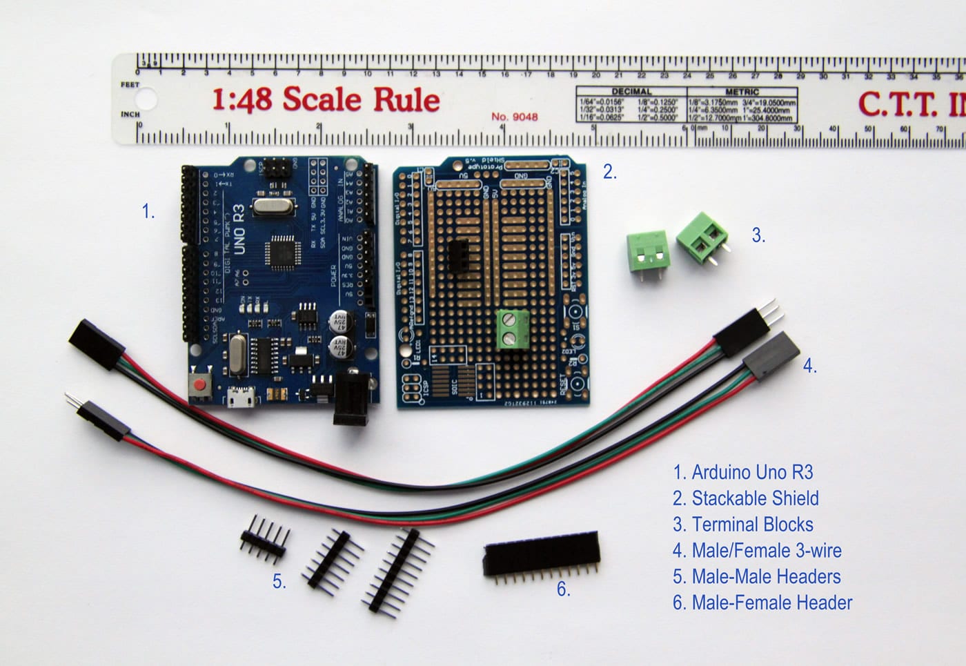
Note that these are SMALL, and require careful handling. The nomenclature for Arduino class items calls any add-on board a “shield.”
The Arduino UNO R3 uses an Atmel ATmega328P chip, which is an 8-bit RISC processor with 32 x 8 General Purpose registers and up to 20 MIPS (million instructions per second) throughput @ 20MHz. It has 32K of programmable Flash Memory, used for Program Storage, 1K of EEPROM and 2K of internal SRAM. It also has two 8-bit and one 16-bit counters, a real-time counter and programmable serial UART. There are 14 Digital Input/Output (I/O) pins (of which 6 can be used as PWM outputs) and 6 analog inputs. PWM is an acronym for Pulse Width Modulation and is used to control motor speeds, robotic servos and the intensity of LEDs and lights, similar to the way a light dimmer works. There is also a 16 MHz crystal oscillator, a USB connection, a power jack, an in-circuit serial programming header (ICSP) and a reset button. Click here for the more information.
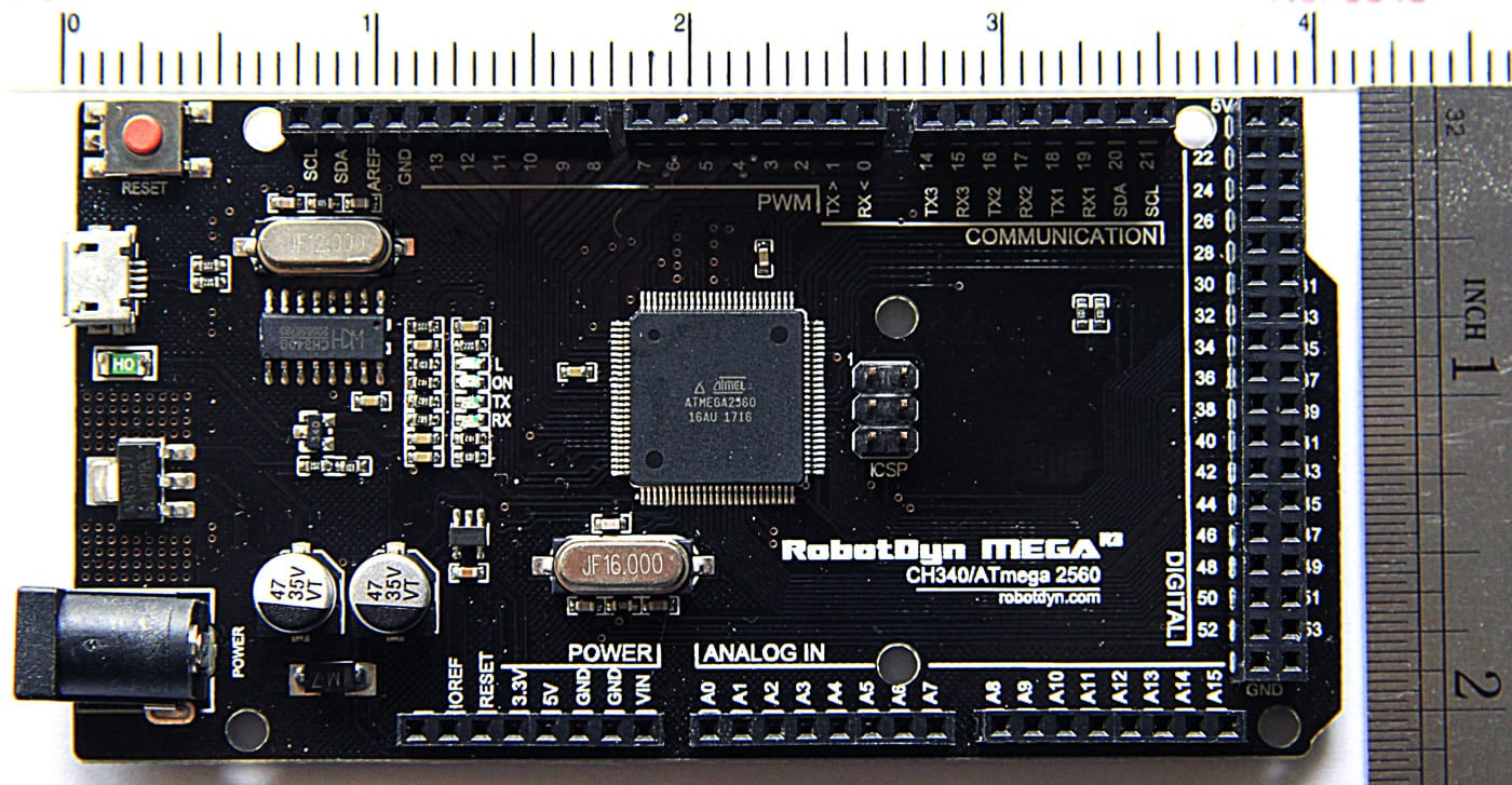
The Arduino MEGA seen above is a microcontroller based on the Atmel ATmega2560 chip instead of the ATmega328P found on the UNO R3. The Mega has 54 digital (I/O) pins, (of which 14 can be used as PWM pins) and 16 Analog Input pins. This board also features 256K of flash memory, 8K of SRAM and 4K of EEPROM. It also has 4 hardware UARTS for communication. There is a 16 MHz crystal oscillator, a USB connection, a power jack, an in-circuit serial programming header (ICSP) and a reset button. It also supports I2C (TWI) and SPI communication. Click here for the complete datasheet.The UNO can operate at 3.3V or 5V while the MEGA operates at 5V. Both have a recommended input voltage of 7-12V (DC). They can be powered via the USB connection or with an external power supply of the appropriate DC voltage. Non-USB power can come either from an AC-DC adapter (think wall-wart) or battery using a 2.1mm center-positive plug inserted into the board’s power jack.
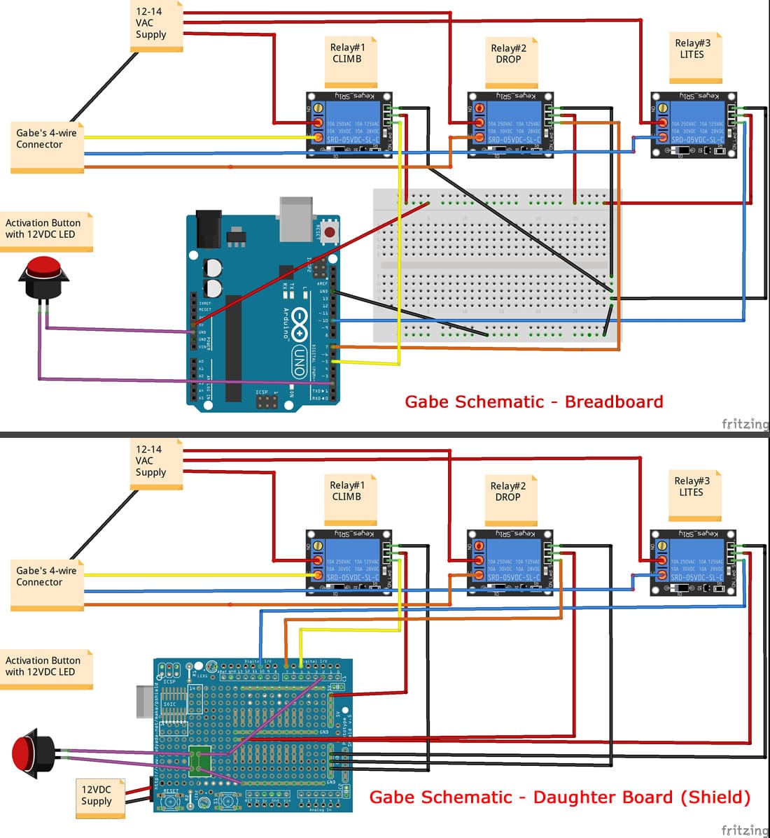
Note that the above diagram is a “breadboard” view of Gabe’s components. The breadboard allows the designer to test the components (using Dupont wires with pins attached to each end, making it easy to plug into the Arduino & breadboard holes), before final assembly and soldering the finished project. Click image for larger view of both Breadboard and Daughter Board versions.
The Air Whistle controller on the previous page made use of a daughter board (these are also known as shields). The shield allows projects to be more modular, so that changing components can be done without having to solder wires and components. I use these shields as often as possible. They add less than $2 to a project, and make it a lot easier to work with the board after installation.
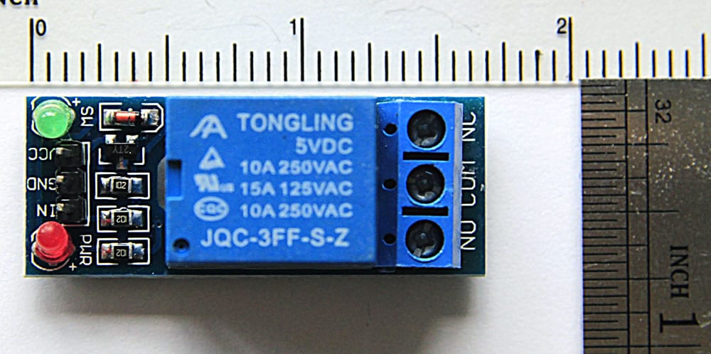
Relays as seen above are used throughout projects as needed.
WORKING WITH BREADBOARDS
Since most Arduino projects begin as prototypes using a breadboard, I assembled a simple example using the amusement park board layout and code. To get a feel for how it works, first click the image above for a larger view, and print it out. Then follow the explanations below.
The breadboard, available in many sizes, has two sets of +/- rails on each side of the board. When a wire is connected to either +/-, on either left or right sides, the entire vertical row will have the same charge. Similarly, each ROW, numbered 1 to 30, are connected in two segments of 5 sockets (a-e) and (f-j), (e.g. Row 1, columns a-e will have the same value as the wire plugged into one socket in this range, but columns f-j will not). This makes is easier to make multiple connections on the breadboard. Columns a-j are not interconnected.
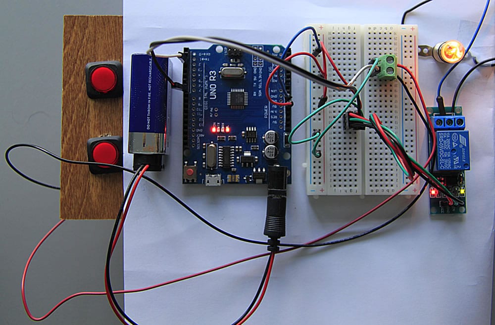
I used a 9V battery to power the board and another 9V battery to power the light bulb connected to the relay (instead of 14VAC power to the amusement park). I have push buttons mounted on a test board to make it easier to test my projects.
The two switch legs (wires running to the push button) are connected to the Green terminal block on the breadboard. Pressing the bottom button, in this case, will result in a HIGH or 1 to show on Pin 2 during a digitalRead() of the pin (buttonPin). If the button is held down for 50 ms, (the debounceDelay) the code will trip the relay via a digitalWrite() to Pin 7 (relay1) and allow power to flow to the bulb for the 15 seconds (runTime). As you can see from the picture, the breadboard is not ideal for installation on a traveling or event fixed layout. If 1 or 2 wires are pulled out, the project will not work properly.
You can follow the code and the connections on the above example. On the left side of the Arduino, the white wire is connected to pin 2 which is buttonPin in the code. The black wire is on pin 7, which is the relay trigger (relay1). On the right side of the Arduino there is a blue wire connected to GND, while the Red is connected to 5V. Both of these wires connect to the – & + rails on the left side of the breadboard.
There are three connections on the bottom side of the relay (Vin, Gnd and In). There are jumper wires in place from the breadboard +/- rails to the 3 pin Male portion of the wiring harness. 5V is connected to Vin (Voltage in), and Ground goes to Gnd. Arduino pin 7 (the trigger) is connected to the In pin. The female plug is connected to the relay.
On the top of the relay are three terminal connectors. From left to right are: the Normally Open (NO), Common (COM) and Normally Closed (NC) connections. In this example, I have 9V+, from battery #2, connected to the COM terminal, while the NC terminal is connected to one side of the light socket. The other side of the light socket is connected to 9V- on battery #2. When the button is pushed, the relay is triggered, and voltage will flow from the COM to NC terminals and bulb lights. In this example there is no connection to the NO terminal.
While all this may seem challenging, playing around with a simple setup like this is a great way to make mistakes, learn, and have fun. Once the basics become second nature, more complex setups are possible.
PROTECTING THE DEVICES
These are very small devices, and benefit from careful mounting and protection, expecially if they are going to be moved around. Plexiglas comes in handy here.
I have drawn most of the common components I use in AutoCad, as seen in the illustration above. This makes it much easier to drill the holes for each piece when I mount the components on Plexiglas. For the AD layout, a plexiglass cover is also installed over the boards.
SENSING AND DOING
We close with a picture of something we mentioned on the previous page. Feedback to systems is an important part of creating appropriate actions on the layout. In fact, there are a large number of components that can be conneccted to let you do amazing things with thise microcomputer systems, on layouts and elsewhere.
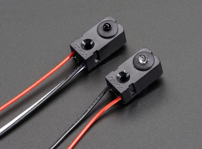
Infrared sensors can be used to detect passage of trains so that gates and lights can be triggered. Other available sensors detect water, tilt, light, motion, heat, gestures, and even speech. And there are even servos, solenoids, fans, gears…. If you’ve ever assembled a Heathkit, a science kit, or similar device, or played with computers, you’ll soon find new uses for these amazing components, and won’t have to spend a ton of money doing it!
Yes, it’s a whole new world, but one that train operators can benefit from getting involved in!