Signal Mania
By Paul Pullen
Do your crossing gates drive you crazy as your trains go around your railroad? I have found that the Lionel contactors are not dependable for the mixed trains that run on the Buffalo Creek Railroad.
Engines on the layout change, as well as the consist of rolling stock from day to day. Some days, the train make-up is totally post-war Lionel, other days it can be a mixed bag of both pre- and post-war equipment, and on other days, it will be completely a pre-war train. Most often, the assortment is made up of a post-war Alco, Union Pacific number 202, which I have equipped with a pre-WWII latch coupler to enable a mixture of equipment.
I also have a scratch-built passenger car that also works as a war- spanning system by enabling post-war passenger equipment to be intermixed with pre-war equipment. If I am running pre-war cars, the weight of the cars varies from the sublime (a stock Lionel pre-war freight car) to the ridiculous (stock Lionel pre-war 8-wheel cars with three inches of auto-body lead added to stabilize their operation).
The weight adjustment on the 153C and 145C contactors are not helpful if you are changing rolling stock as often as I do, or with the variation of the weights for the cars in the trains. The engines generally have tripped the crossing gates, but the rest of the train will be crossing the contactor and the gates will raise. This is not a very “proto-typical” method of operation for grade crossings. This prompted me to take another look at the operation of my crossing gates.
The first move in this re-evaluating the operations of the crossing gates involved in the prying up of one of the outer rails of the ‘0’ gauge track. When removed, I cut ‘fish paper’ (file folder strips) to insulate the outer rail from the rest of the track, and reassembled it with no metal track pins. In most cases, I inserted part of a wooden kitchen match to line up the rails. When the tracks were assembled, I soldered a lead to the ‘insulated’ rail and ran it to the crossing gate. The other connection on the crossing gate went to one side of the accessory transformer I use to power accessories. The other connection from the accessory transformer went to the common rails of the track. It seemed to me to be an easy way to get the crossing gate to operate when any cars on the train were in the insulated trip rail area for the crossing gate. Theory says that any car or engine that bridged the insulated rail would hold the crossing gate down until all cars had passed through the trip area.
As would be expected, the engine immediately caused the crossing gate to drop, but after the engine passed the trip rails, the operation of the crossing gate became very spotty. It seems even pre-war cars did not dependably maintain the crossing gate in the down position. The lack of operation with metal wheels and axles has to be due to dirt deposits on the wheels or between wheel and axle on the older cars.
This lack of proper operation drove me to frustration city. I was ready to not use the crossing gates at all.
However, I did realize that since the engine would dependably cause the crossing gate to lower, I could count on system to latch the crossing gate in the down position, if I could devise a method of ‘timing out’ to raise the gate after the train passed the grade crossing. Having been “trained” (pun intended) in the U. S. Army in electronics, I had a background of working with the type of circuits I needed for the job.
The first method of doing this involved both a trip position and a release position. I set up a relay latching circuit that would lock the crossing gate in the down position as the train approached the grade crossing. Then, after the entire train had passed the grade crossing (one block later), the engine would hit a second insulated section, causing a second relay to pull in and release the latched relay. This made for a very solid, crossing gate controller.
However, it only would work with a set direction of train. If your line is single track railroad going east and west, or north and south, when you reversed direction, the gate would not work until the engine had passed the grade crossing with no protection from the gates. Then the gates would come down and latch permanently until the next train passed in the opposite direction or continued around the main line and reached the trip track again. Then the gate would rise while the train again approached the grade crossing. That would never do, for the railroad would be subject to the flock of ambulance chasing lawyers who monitor accident reports.
I then went to work with a batch of junk parts to devise a system to do just this. I designed a relay latching mechanism to control the crossing gate and also start a timer to release the relay. The first relay latches, and applies power to a 555 integrated circuit that times the gate hold time, then activates a second relay to release the first relay. When the second relay pulls in, the circuit resets the first relay, power is removed from the timer circuit resetting it, the crossing gate rises and traffic can cross the grade crossing until the next time a train approaches. With an insulated section on each side of the grade crossing, the crossing gate will drop on the approach of a train in either direction, and remain down for the duration of the timer circuit. The problem with the crossing gate is solved.
Are you lost by that quick explanation?
Probably many of you are, so I will try to explain the operation of the circuit in a layman’s language. The circuit consists of three separate parts to operate crossing gates. These parts are:
1. Power supply
2. Relay latching circuit
3. Timing release circuit
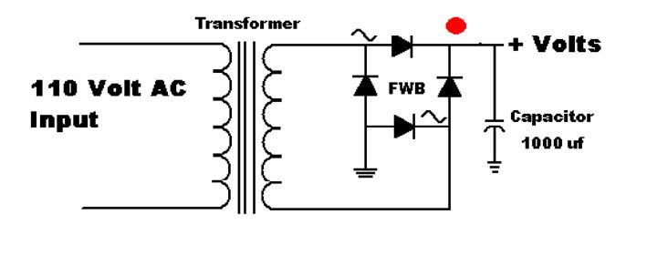
First, the system needs a power supply. I have been experimenting since I build my first control circuit (I have now built 3). The power supply is simply a small transformer, a full wave bridge (FWB) rectifier, and possibly a capacitor that is dedicated to accessory (read crossing gate) control operations only.
Figure 1 shows the wiring of power supply and it consists of a low voltage power transformer. The FWB + lead is connected to the common rail. The FWB – lead goes to one side of the coil winding on the relay Kl. K1 used in the circuit is a four pole, double throw relay. The other side of the relay coil is connected to the insulated rail on the layout. The connection between the relay coil and the insulated rail is also connected to the common lead in contact K1a. The Normally-Open (NO) contact in K1a is then connected to the common contact the second relay, K2a. The Normally-Closed (NC) contact in K2a is then connected back to the + voltage line. This simplified version of the control relay wiring to track does not show the contacts that control the accessory (K1c or K1d). One accessory control lead number goes from the NO connection of contact K1c directly to an accessory, such as the crossing gate. The other accessory connection connects to one terminal of the accessory power supply. The common terminal of relay contact K1c then connects to the other power lead from your accessory control transformer.
Operation of this locking circuit is as follows. The train enters the insulated rail area, and connects the ground rail to the outer insulated rail. This causes current to flow through relay coil K1, which closes all contacts used. K1a supplies power after the train leaves the insulated track so the crossing gate remains in the down position. When the timer circuit times out, it causes K2a to open, thereby releasing K1, and opening the K1 contacts until a train next appears in the insulated track. (This drawing only shows one of four sets of contacts Kla, Klb, Klc, and Klc for simplicity. All contacts move simultaneously, giving the ability to apply power to a timer circuit to replace the push button, and also control one or more accessories.)
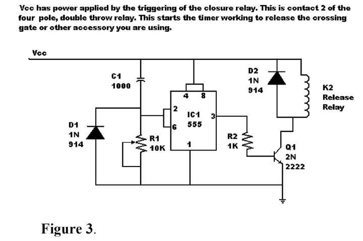
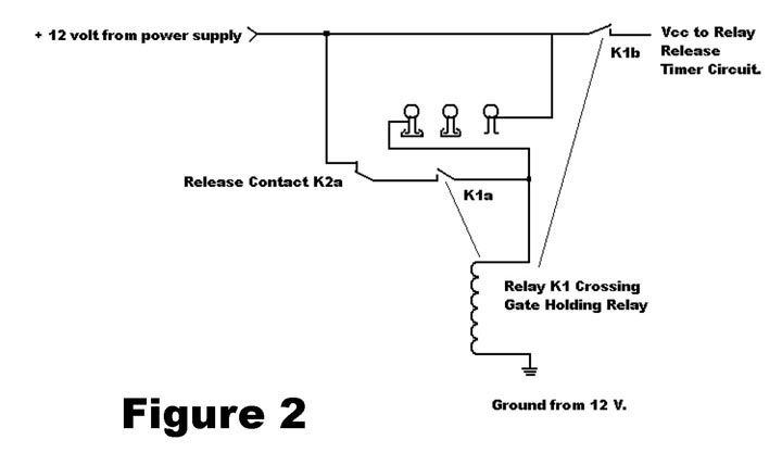
The third part of this system is the timer circuit. The operation of the timer circuit depends on the operation of the latching relay. Without K1, the system will not work. As shown in Figure 2, contact K1b’s NO contact is connected to the point labeled Vcc on Figure 3. This point is the same as DC+ in Figure 2 or FWB+ in Figure 1. K2a’s common connection is connected to the Normally-closed (NC) contact of relay K2, which is part of the timing circuit.
The common connection to relay K1 is then connected to the full wave bridge’s + terminal. The circuitry depends on a generic, run of the mill, integrated circuit timer, the 555. Vcc is applied to the circuit when is pulled in by a train passing down the insulated track. K1 latches in closing all K1 contacts and lowering crossing gate at the grade crossing. The combination of Cl-R1 is a charging circuit that triggers the 555. The approximate time involved in the triggering the 555 can be calculated by multiplying the capacitance of Ci times the resistance of R1. The circuit as shown uses a 1000 micro-farad capacitor and a 10,000 ohm adjustable resistor. The maximum time involved with this setup is then .001*10000 or 10 seconds. That may not look right, but the 1000 micro-farad capacitor is in reality 1000E-6, which is .001. The adjustable resistor can be used to vary the timing of the delay from 0 to 10 seconds. When the 555 triggers, it turns on the transistor Q2 and that causes the relay K2 to close long enough to release the holding circuit in relay K1. The system then will sit and wait until your next train approaches the grade crossing.
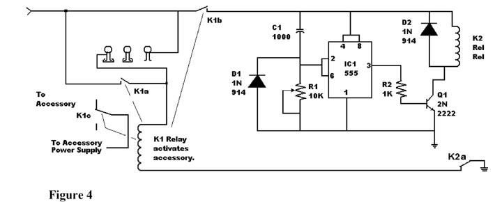
The full schematic is show in figure 4.
This has brought up another type of control circuit, one that will cause the operation of signals on the railroad. I have been fooling with a complex circuit that uses CdS cells, but have decided that it would be too flakey for operations because of differing light levels in the train room. If you set it for normal light, it might not trigger in low light levels (read night time). So I have done a little design using a set of 4 pole double throw relays, and if your main line has five blocks or more, you can use this system. Once again, you will be working with a DC power supply to operate the relays, and the second accessory power for the track side signals. Theory is that you have one contact on each relay for the lights on the track side, the second controls the latching of the relay changing the block signal from clear to occupied, the third controls the resetting of the block two blocks behind your train. This leaves a fourth contact to be used to power a dead spot to stop the train at an occupied block if you want. I did not draw that segment of the circuit for you, but it would be an easy addition.
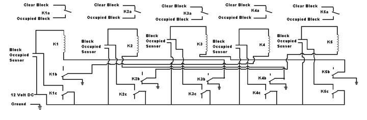
The theory of this operation is that train goes past block signal A, causing the indicator to change from green to red, and continues on down the main line. When this train passes block signal B, block A is not clear, so block A will continue to display a red signal. Block B’s indicator goes red because the train is now transferring from block A to block B. When the train reaches block C, it triggers the same change for indicator C to go from green to red, however, now block A is clear, so the third contact of relay K3 resets relay K1, causing block signal A to go from a red signal to a green signal. Block A is now clear, so when the train again approaches block A, it can continue on. If you wire a set of block signals and want to have them appear to be working, this is a routine you can use. All it requires is a minimum five block main line. Any number of blocks more can be used with the proper clearing of a block when the train reaches two blocks ahead of its present position. The diagram of a 5 block system is shown in figure 5.
Operation of Block Control Circuit:
The diagram that this is related to is the 5 block circle that is pictured after this introduction. The minimum number of blocks to operate “automatically” is 5. This will leave you with a red block signal in the block the train is leaving, as well as the one the train is entering. The blocks behind will then be cleared for a “new” train to enter, but will always have a red signal on the two blocks that the train is leaving and entering.
The small blocks around the track are to signify the location of an insulated track. There are 5 of them in this diagram. The heavier lines across the track are the location of block signals on the main line.
In this description of the operation, I will explain the operation of each block control relay, in this case identified as K1 to K5. The important contacts I am going to call out are the locking contacts K#c and the releasing contacts K#b. The signals are controlled by either K#a or K#d if you are using the 4-pole, double throw relays called out in the parts list.
Contact K#a is the signal control for block #, using both the NC (clear signal) and the NO (occupied signal) contact for the same section. K#c uses the NO contact to lock in the relay when the train crosses into an insulated section. Contact K#b uses the NC contact to release the signal K#-2 when the train enters the insulated track.
Block signal indicator lights are connected with the green light connected to the NC contact on K#a and the red light connected to NO contact of K#a. The common lead for contact b is connected to one side of your accessory power, and the other side of accessory power is connected to the common on the block signal.
The size of the block is set at a minimum of the length of the longest train you will operate on the right-of-way. The train can take up the entire area of a block when in operation. If the train is in block 1 (as shown) when powered up, Block 1 signal will immediately go red to protect the rear end of the train. In order to do this, relay K1 is energized, and contact K1c latches connecting D.C. power to the relay coil across the As the train proceeds counter-clockwise around the track, it has a green signal at block 2. As it passes the block signal, the block signal will goes from green to red. Relay K2 activates (pulls in) and contact K2c supplies power across the insulated section maintaining the relay in the activated state. At this time, contact K2b opens, but since another signal has not been activated, it does not reset the previous block to clear.
As the train continues around the main line, it reaches block 3. When it enters into block 3, the relay K3 activates and K3c closes and locks the relay in the active state changing Block Signal 3 from a green signal to a red. Simultaneously, the normally closed section of contact K3b opens, and this causes relay K1 to de-activate resetting Block Signal 1, changing from red to green. Now if we look at the signals, Block Signal 2 and 3 will be red, while Block Signals 1, 4 and 5 will be green.
The train will proceed to Block 4, and when it passes the signal and enters the block 4 insulated track, it will cause relay K4 to activate, closing contact K4c and latching the circuit. The lights connected to K4a will change from green to red, and K4b will open releasing relay K2 and resetting Block Signal 2 from red to green.
The train will then continue to Block 5, and passing it, it will cause K5 to activate. This will latch relay K5 with K5c, change the Block Indicator from green to red with contact K5a, and deactivate relay K3 by opening contact K5b.
Now the train has again reached Block 1. When it passes the signal and enters the insulated rail section, K1 once again activates, closing K1c to hold it in operation, changing the Block signal from green to red with K1a, and releases K4, resetting the block signal 4 from red to green. And so it goes.