Setting Up a Model Railway
Reprinted by Paul Pullen
{Editor’s Note}:
Quite a while ago, Paul had asked about the possibility of forwarding a part of a book that covered setting up floor trains that his grandfather had purchased in the late 1930’s. According to TCA Librarian Jan Athey “the work in question was published between 1/1/23 and 12/31/78 and the copyright owner did not renew it. Therefore this work is now in the public domain and can be used in the article.”
The following is reprinted from:
The Home Workshop Manual
Edited by Arthur Wakeling
Published 1930, Popular Science Publishing Co., Inc.
It is an excerpt from chapter IX, entitled “Model Making.”
In the operation of a model railway, there comes a time when you tire of watching the train go round and round a plain circular or oval track. And then, quite logically, you decide to expand it into a more comprehensive system. As a result you buy yourself some more track, a few switches, and such other accessories as happen to appeal to you. This process is repeated several times. Eventually, your model railway looses all semblance to a real railroad and becomes, instead, a conglomeration of weird curves and impossible sidings that looks like a centipede in convulsions.
Careful planning will save you money and result in a more interesting and satisfactory model railway.
The first step in your planning should be to decide what, in your own mind, would constitute an ideal model railway based on what you know of real railroad practice. Then you take a pencil and paper and figure out how near you can come to that ideal.
Of course, a perfect model railway would be one that duplicated in miniature every piece of rolling stock, every foot of track, and all other apparatus found on a real railroad. Obviously that degree of perfection is an impossibility. The best you or anyone else can do is to decide on some definite degree of accuracy your model railway and strive to be consistent in maintaining it.
The foundation of any railway, whether full size or miniature, is the track layout. Real railroads have stretches of track hundreds of miles long. And right here you strike your first compromise with accuracy. The space available precludes duplicating such a layout in miniature. You will have to use your imagination and consider that long stretches of track have been compressed lengthwise to a far greater extent than would be permissible in a true scale reduction.
Since your track will of necessity be foreshortened, it seems logical to have the locomotives and cars somewhat shorter than scale length, provided, of course, that they are otherwise of the proper dimensions.
The same reasoning applies to the curves in the track. You cannot duplicate the long, easy curves of full size railroad right-of-way. Your curves must be much sharper in order to be practical in the space you have available.
The question of space governs the possible track layout. The larger the space the more elaborate the layout can be, but careful planning usually will result in a satisfactory and workable track layout even in a small space.
There are two general types of track arrangements in common use in model railway construction. One is called the “point-to-point system” and the other is the “continuous run.”
In the point-to-point system the track layout includes two terminals with one or more tracks connecting them. Trains are run from one terminal to the other just as in real railroad practice. This arrangement is most popular when clockwork locomotives are used or when the space is particularly suited; for instance, when the track must be laid in two small rooms with a long hallway connecting them.
The continuous-run track layout is far more popular.
With a proper terminal it more nearly duplicates actual railroad practice because the train can be run around a sufficient number of times to simulate a long trip. You may, indeed, have one or two small way stations on the track and consider that the distance between them consists of ten or fifteen laps of the track instead of the few feet that actually separate them. Of course, it requires a bit of imagination to make this seem real, but if you didn’t have a good imagination you wouldn’t be interested in model railways anyway!
One limitation on the size of your model railway over which you usually have no control is the floor space that you may use for the purpose. Just so much space is available, and your problem is to work out the most practical track layout within the dimensions of the floor.
You do not, of course, have to lay the track on the floor unless you want to. It often is desirable to erect a shelf or bench around the walls and lay the track on it. This plan has much to recommend it. Working on the railway and operating it on a waist-high shelf is considerably less hard on the back muscles. Also, the track is not so likely to be damaged, and the space under the shelf can be used for storage. When the dimensions of the room are small, you may even erect a wide shelf at waist height and then a narrower shelf just above it with a grade connecting the two levels.

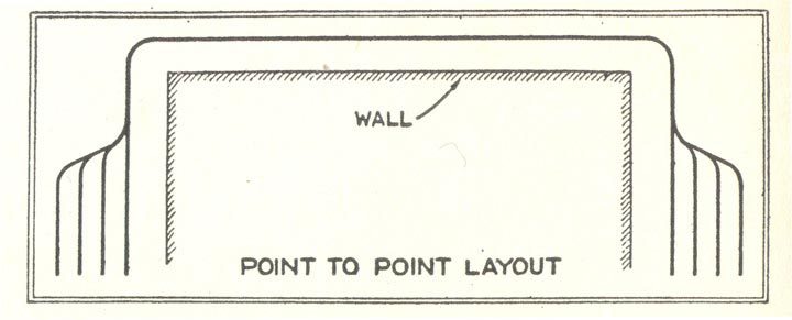
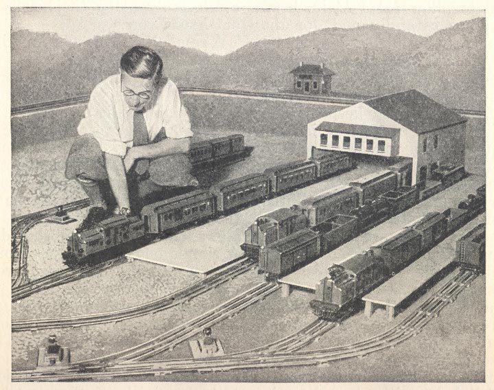
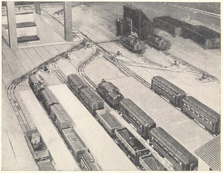
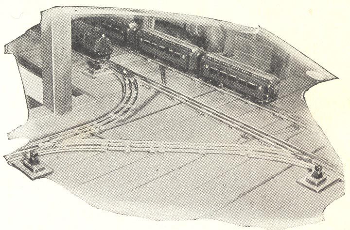
It is difficult to give any definite directions as to the actual track layout. Typical point-to-point and continuous-run layouts are illustrated above, but a book could be filled with the possible track arrangements that could be worked out even in a small room. However, there are certain general principles that should be kept in mind. First, remember that nothing is to be gained by making the track layout needlessly complicated. Second, observe the common railroad practice of keeping switches off the main line as far as possible. Do not force the train to run over a long succession of switches each time it makes a circuit of the track. Put a switch or two on the main line and let the other switches lead into the siding thus formed.
You can use a single main line around the room; or, if there is space, put in double track with not over two cross-overs arranged so that you can switch the train from one track to the other no matter which way it is going.
Place your terminal where you can get at it as easily as possible to do the necessary hand operations of making up trains and handling them in sidings. Unless the room is very large, be content with one terminal and one or two passing stations located at whatever points on the main line seem most suitable.
A single switch on the main line may be used to bring trains into the terminal, but a WYE will permit you to start trains off in either direction and come back into the terminal by way of the other branch of the WYE. It also will permit you to turn a train without taking it off the track.
The caution about switches on the main line does not apply to the terminal. You will find that, as your system grows, every siding you can find room for will prove useful for car storage and switching.
It also is desirable to have at least one long siding with a switch from the main line at each end so that you can hold a train on the siding while a train traveling in the opposite direction passes or so that a slow freight can get out of the way of a fast passenger express.
To start the actual plan, take a large piece of paper and mark on it the out-lines of the room, using a relatively large scale. One inch to the foot will do very nicely. This will give you a fifteen-inch square for a room measuring fifteen feet in both directions. Now, with the suggestions above mentioned in mind, lightly sketch a proposed track layout. Over this light outline, draw a plan using a scale reduction for the curves of the track. Locate all the switches and track you expect eventually to install even if you don’t expect to build all of it right away. Then you can work to a definite plan. Furthermore, if the plan is accurately drawn you can calculate from it how many sections of track you will need to complete each addition.
It is one thing to draw the track on paper and sometimes a much harder problem to make the standard curved and straight track sections fit together to form the actual layout. The WYE leading from the main track into the terminal probably will give you some trouble. Of course, you can make a WYE out of standard track sections if you make it big enough, but to get a compact WYE you will need to cut some special lengths of track.
The simplest way to lay the WYE is to connect the curved end of a right-hand switch to the straight end of another right-hand switch by means of one curved section. Then take two straight sections and a left-hand switch and cut off enough of one of the straight sections so that you can line up the curve of the left-hand switch exactly with the curve of the WYE switch. Complete the job by cutting straight sections to join. A WYE assembled as described is shown below.
There are two ways to cut track to any desired short length. One is to saw it at the desired point with a hacksaw fitted with a very fine-toothed blade. A 32-tooth-to-the-inch blade will do. This method is not as easy as it looks, however, because the thin sheet steel catches in the blade. Another method is to cut the track with a pair of tin snips and then reshape the track ends-they will have been flattened out of shape-by the careful use of a pair of round-nosed pliers.
You will find many places in any comprehensive track layout where cutting off a standard section will permit an arrangement that otherwise would be impossible.
The smooth operation of the locomotives and cars over the track and switches cannot be expected unless care is taken in laying every section. Be sure that every pin fits tightly. One loose pin may hinder the flow of electric current to the locomotive over a considerable section of the track and result in irregularity and uncertainty of operation.
Take pains to see that straight stretches are really straight and that they will stay that way. This means that each section should be fastened to the floor or bench with screws. One screw close to each joint will do. Do not use nails. You will have trouble pulling them if you desire to make any changes.
Track can be laid straight by stretching a string an inch or two above the floor or bench and then measuring from the string to the nearest rail. This is a much better method than to rely on sighting the rails.
Banking the curves at the ends of long straight stretches will help to prevent derailments. Start the banking on the straight section before the curve. Small pieces of wood under the outer ends of the ties will give sufficient bank and the screws that clamp the track will hold them in place. A banked curve is shown above. This curve is banked about five degrees from the horizontal.
Avoid S-curves made by connecting two curved sections together. If you must have an S, insert at least three quarters of a straight section between the curves.
A track layout that includes grades for the locomotive to climb will prove more interesting than a layout where all the track is on the level.
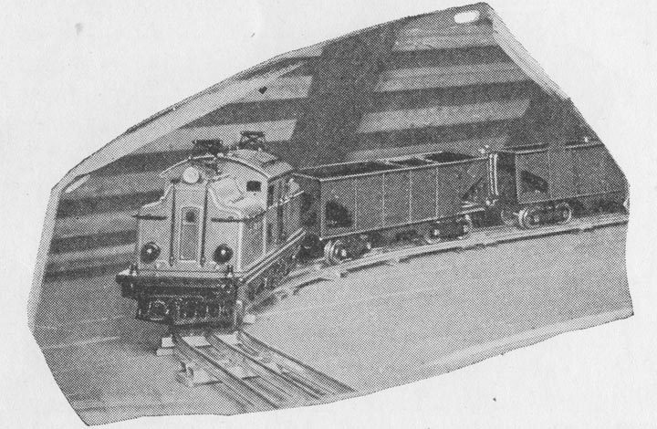
Do not make the grades too steep. The slightest amount of oil on the track will cause the locomotive driving wheels to slip, and the train will stall if the grade is too heavy. Real railroads rarely use a grade steeper than one in thirty, which means that the train climbs up one foot for each thirty feet of track. Any well-built model electric locomotive will climb such a grade and pull the usual number of cars without undue wheel slippage. The heavier double-motor locomotives will start a full train from a standstill on such a grade. Below shows a train climbing a grade of one in thirty.
Space limitations and the arrangement of your track layout may, of course, necessitate a steeper grade. This is permissible if the grade is short and there is a straight run at the bottom of the grade so that the locomotive can get a running start. Another way out of such a difficulty is to make the grade quite steep near the bottom where the momentum of the locomotive will help to carry it up. The upper end of the grade should then be made a more gradual climb.
One of the simplest ways to install a grade is to take a single board the length of the grade and cut some short pieces, beginning with a 1-in. piece, then a 2-in. piece, a 3-in. piece, and so on. These can be placed at uniform intervals under the long board and the spacing between them will determine the grade. For a one-in-thirty grade, for example, the graduated supporting pieces should be thirty inches apart. If the board in which the track is fastened is 5 or 6 in. wide and 7/8 in. thick, the supports may be as much as thirty inches apart, but if a thinner board is used it will be well to double the number of supports by cutting them in inch steps.
You may not be so fortunate as to be able to put your track down permanently. However, it is possible to make a satisfactory portable track layout, although of necessity it cannot be made as elaborate as a permanent installation.
Obtain from the nearest lumber dealer several sheets of plywood. The three-ply sheets a fraction of an inch less than 3/8 in. thick will do. Instead of fastening the track to the floor or a permanent bench, cut lengths of plywood to fit under the track. This will permit you to take up the track in long sections without danger of bending it. As plywood is limited in length, usually the maximum length of a single strip cannot be over 5 ft.
The terminal can be mounted on a single piece cut to the proper size. By carefully planning the breaks between sections, you will be able to build a track layout that can be taken up in sections and stored in a convenient closet in just a few minutes.
Portable grades can be made just like permanent grades except that the plywood is used instead of a thick board and ‘the supports will have to be attached to the track board by means of cheap iron hinges to allow the supports to be folded against the track board when you wish to store it.
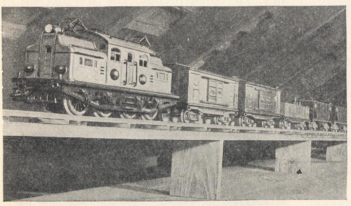
Real locomotives with strings of passenger or freight cars behind them go by with a tremendous roar, so that the noise of a model train as it goes around the track is quite natural and realistic. However, the people living in the rooms directly under the floor where the model railway is installed may object to the noise. A permanent installation cannot be muffled to any noticeable extent if the track is fastened directly to the floor. Putting strips of felt under the track will not do much good because the vibrations still will be transmitted to the floor boards by way of the screws. The only practical solution is to mount a the track on boards just as though you intended to make it portable and then glue strips of felt under the boards. The felt will prevent any direct vibrations from being transmitted to the floor.
OPERATING A MODEL RAILWAY SYSTEM
A model railway is, after all, merely a miniature edition of one of our real railroads. And, subject to the limitations of time and space, the model railway owner is faced with all the problems confronting the management of a real railroad.
The most important of these problems, once the model railway is constructed, deal with maintaining the power supply, the locomotives, the rolling stock, and the track in first-class condition.
Unfortunately, many have the idea that model railways are similar to other mechanical toys sold to children. Nothing could be farther from the truth. In proportion to their size, the better makes of model railways are, in every detail, as well built as their large prototypes.
Power obtained from dry cell batteries is satisfactory for operation in every respect save one it is very costly. Consequently batteries should be crossed off the list as a power source if the house is wired for electric lights.
When direct current is available, it is possible to obtain the low voltage current required by the model railway by the use of a voltage reducer consisting of special resistance elements. The vast majority of homes, are, however, supplied with 110 volt, 60 cycle alternating current. This is ideal, for it permits the use of a step-down transformer wound to supply exactly the required voltages. There is no wasted power, a necessary evil with the direct current reducer.
Moreover, a model railway power station equipped with a transformer conforms more closely than most people realize to actual practice on a real railroad. If the transformer heats excessively, it is an indication that you are drawing too much current from it. The remedy is to divide the load and use two transformers, each one handling part of the load (see below).
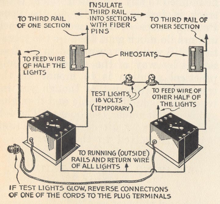
Do not attempt to operate two transformers in parallel, as you are almost certain to get in trouble.
The locomotive on the model railway, as on the real railway, is at once the most important and the most interesting unit in the entire equipment. On most real electrified railways, the current flows through an overhead wire and is collected from this wire by means of pantographs on the top of the locomotive. On model railways the best practice is to use an insulated rail placed between the rails on which the wheels run.
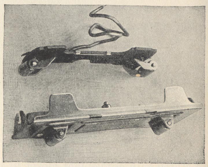
A current collector (see above) is fitted to the bottom of the motor frame in such a way that the small steel or brass rollers are held by springs in good electrical contact with the third, or insulated, rail. The electric current flows between the third rail and the running rails by way of the current collector rollers, the motor, and the driving wheels of the locomotive.
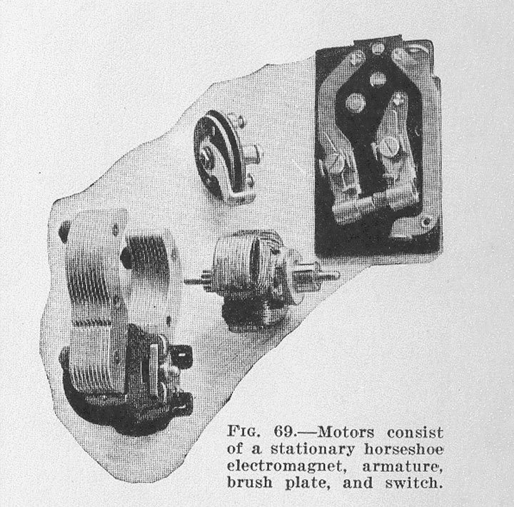
The motor consists of a stationary horseshoe shaped electromagnet, a rotating armature, a brush plate, and a reversing switch. The armature is fitted at one end with a small gear and at the other with a commutator made of three heavy copper segments. The current flows through the winding on the stationary magnet and also through the winding on the armature by way of the brushes, which make sliding contact with the commutator. In the finest motors, one of the brushes is of a graphitic carbon composition and the other is of tightly rolled copper gauze.
For reversing, a switch changes the direction of current through the armature with respect to the stationary magnet. In consequence, the magnetism in the armature is reversed in polarity and it rotates in the opposite direction.
The rollers of the current collector must be kept clean and should be replaced after long continued use has worn, grooves in them and roughened the surface so that a good electrical contact is no longer possible. Trouble is almost never experienced with the stationary magnet, except perhaps a loose connection at a terminal wire.
Though the armature winding also gives no trouble, once in a while one of the wires soldered to the commutator segments will come loose. When this happens, the motor loses almost all its power and there is severe sparking at the brushes. The simplest remedy is to replace the armature with a new one; but if you are handy with the soldering iron, you can locate the loose connection and resolder it.
The condition of the brushes and the way they make contact is of vital importance. Whenever you find that a motor runs well in one direction but not so well in the other, the trouble is almost surely in the brushes.
The best way to clean the commutator is to use a clean rag on the end of a small wooden stick. Give the commutator a wipe after every few hours of running and occasionally give it a thorough cleaning.
Never, under any circumstances, put any oil on the commutator. It should be operated absolutely dry. The carbon brush contains sufficient graphite to afford proper lubrication. In the latest types of model locomotives the brushes are held in their tubular containers in such a way that they cannot rotate. In consequence, they quickly wear to a perfect fit against the commutator.
In general, if the motor runs poorly with but little hauling power, the trouble is most likely to be a dirty commutator. If the locomotive refuses to run at all or runs in a very jerky fashion, look for a broken or loose connection somewhere in the wiring or for a worn-out brush or broken brush spring.
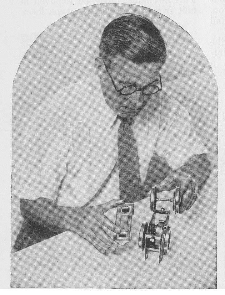
The latest thing in model electric locomotives is a motor built so that it can be taken completely to pieces in a few minutes by the aid of an ordinary screw driver (see above). Obviously, the new motors are much easier to clean and repair than the older types. Loose connections are almost an impossibility in these new motors, because all necessary connections are made by way of rigidly attached brass bus bars and spring plungers.
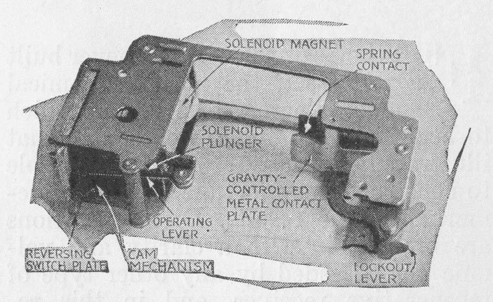
The more expensive grades of model electric locomotives are fitted with automatic reverse mechanisms (see above). This mechanism may be removed as a unit from one of the new type locomotives. A solenoid electromagnet pulls a lever into engagement with a cam mechanism in such a way that the reversing switch plate is thrown alternately first one way and then the other.
Current from the third rail through this solenoid magnet is controlled by a contact on the end of a flat metal plate so hinged that gravity, when no current is flowing through the motor, pulls the heavy end of the plate down and closes the contact.
When the current is turned on, the pull of the solenoid reverses the switching plate and immediately thereafter the magnetism of the stationary magnet of the motor pulls down the contact end of the metal plate and stop the flow of current through the solenoid. When the current is shut off to stop the locomotive, gravity swings the metal plate back against the contact so that the solenoid will function when the current is again turned on.
The reversing mechanism requires no attention whatever. It should not be oiled at all. If your locomotive develops the unpleasant habit of suddenly reversing itself, or the reverse mechanism seems to falter and stutter, look for trouble with the commutator or collector rollers. The reverse mechanism cannot function properly if the current flow is interrupted at frequent intervals by a dirty commutator or worn collector rollers. Each time the current is interrupted the effect on the mechanism is exactly the same as if you deliberately shut the current off by means of the regular control switch.
The importance of the proper lubrication of fast moving machinery has been dinned into everybody’s ears so frequently that it seems unnecessary to repeat the advice as applied to model electric railways.
Bearing pressures are relatively light, bearing speeds at some points are quite high, and the lubricant that cuts friction to the minimum under all such conditions is a light, high-grade machine oil such as would be suitable for typewriters, sewing machines, and other similar light machinery. It will be found that a very small quantity of oil will perfectly lubricate the armature bearing. Any excess oil simply smears out around the bearing where it can do no good and serves only to collect dust.
The armature bearings of the motor and the gears should be sparingly lubricated at least once for each hour of running. The drive-wheel axle bearings should be lubricated in the same way after each two or three hours of running. The tiny bearing at each end of each roller on the collector plate should be lubricated just enough to keep it from running absolutely dry. Any excess oil on the collector roller bearings will work down on the rollers and smear all over the third rail.
If you are fortunate enough to own locomotives fitted, with the new style motors that can easily be taken apart, it is a good idea to pull them completely to pieces every two or three months and carefully clean the excess oil and dust from each of the parts.
A broom straw or a piece of fine wire is the best article to use in applying oil to the bearings and gears. The axles of each passenger and freight car should be sparingly oiled once every month or two. The only other thing on the model railway that requires lubrication is the turntable, the gearing of which may be oiled at very long intervals.
When, many years ago, the pioneer railroads first began to carry passengers and traffic in a commercial way, the crude locomotives of those days frequently broke down. However, it is a curious fact that the majority of accidents on those primitive railroads were due to track failure. Instead of the immensely strong rails of heavy steel now in use, the first locomotives ran on rails made of thin strips of strap iron insecurely bolted to wooden stringers. Every so often a piece of strap iron would come loose, curl up, and poke a hole in the boiler of the locomotive. Even today, a vital point of difference between one of our crack railroads and a backwoods branch line is in the quality of the roadbed.
Each section of model railway track as it comes from the factory is exactly straight if it happens to be a straight section, or a perfect segment of a circle if it is a curved section. But even perfect track has to be carefully laid.
Some oil is bound to work down on to the track from the wheels and on to the third rail from the collector rollers. Dust settles and in time the rails become coated with a gummy film that reduces the pulling power of the locomotives and interferes with the flow of the electric current.
If more than an occasional spark can be noted under the collector rollers as the locomotive speeds around the track, it is conclusive evidence that the rails need cleaning. Plain rags applied with plenty of “elbow grease” will serve to clean the rails.
Switches should be cleaned along with the rest of the track. The electrical mechanism that operates the switch is purposely enclosed in a metal case in such a way that you can’t get at it. If an electric switch fails to operate, first try a slightly higher voltage. If it still refuses to function, send it back to the factory. After a switch has been in use for some time, especially if you have operated heavy locomotives through the curve of the switch at high speed, trouble may be experienced with derailments of the cars. This is due to the weight of the locomotive bending the curved rail on the movable plate as it hits the switch. The remedy is simply to bend the rail back into place.