Lionel’s Textbook of Model Railroading (Part III)–Scenes from a Dream Layout
By Joseph H. Lechner
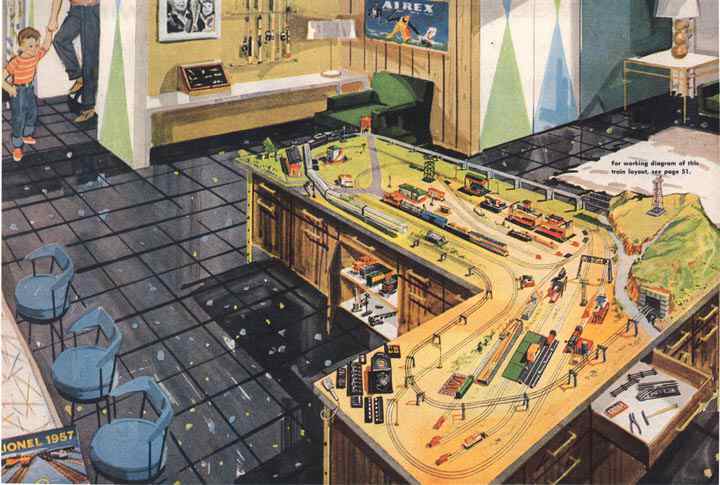
Lionel’s 1957 dream layout was designed to be built on two 5’ x 9’ plywood panels arranged in an “L” shape. As a piece of recreation-room furniture, it was stylish and modern-looking; as a Lionel promotional icon, the table’s shape held profound symbolic meaning; as a model railroad, the panels divided the layout into two distinct groups of scenes. In October’s issue, we examined the left panel, which featured a small-town depot, an interlocking plant, and an industrial area.
This month we will look at the right panel, where we find a mountain scene, a service facility, and the railroad’s main control panel.
Scene 4: The Mountain
Because they were built on plywood foundations, toy train layouts tended to be flat. Any real railroad would have been absolutely delighted by flat terrain, because level track cost less to construct and was easier to operate. Nevertheless, flat layouts could get monotonous. Height added interest and drama. Mountain railroading was more challenging, and also more dangerous. Climbing mountain grades and going through tunnels added to the illusion that your train was going somewhere important and far away.
One of the first accessories that many young Lionel railroaders acquired was a #110 trestle set. For only $5.95, it allowed you to raise your track off the table, up to a maximum height of 5.5” and back down again. This was high enough to construct an over/under layout where one train could pass over another. Toy trestle sets worked well if you assembled the piers correctly and anchored them to the table, but visually there was something missing. Rails and ties hung in mid-air between piers with no visible means of support. On a real trestle, there were heavy wooden beams or steel girders under the ties to support them.
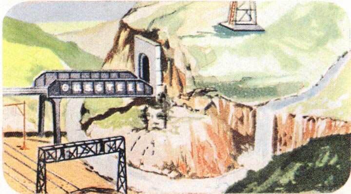
The designer of our dream layout combined multiple tracks, trestles, bridges and mountains to create an important-looking scene. It looked like a remote junction where two Class 1 railroads crossed deep in the Appalachians, rather than merely some toys arranged on a table top. The composition of this scene reminds me of a famous photograph by the late great O. Winston Link. “Hawksbill Creek Swimming Hole” showed some kids swimming at night in a river. A highway crossed the river on a concrete bridge, and the Norfolk and Western Railway crossed both on a high steel trestle.
The elevated track in this scene passed over the railroad yard, crossed the river on a through girder bridge, then plunged directly into a tunnel. Scoffers have complained that a real railroad track wouldn’t have gone directly from a bridge to a tunnel, but they are wrong. I know for a fact that there was just such an arrangement at Bellows Falls, Vermont. I’m sure that there were similar situations along the N&W and the Virginian as those roads twisted through the Appalachian foothills in search of coal.
Parallel tracks in the foreground, spanned by a #450 signal bridge, gave the illusion of a high-speed double-track mainline through the wilderness. Actually, these tracks were part of the service yard. Just out of this picture to the right, the rear track led to the icing station and the front track led to the transfer table. Part of the genius of model railroading is to make things seem much bigger than they really are. This layout succeeded brilliantly; a train that had moved less than 24” from the icing station to the signal bridge appeared to have traveled for miles.
Water enhanced the illusion of distance by creating a barrier. The parallel tracks at the front of this scene were less than a foot from the mountain, but the river separated them visually. Similarly, the stream that ran down the side of the mountain appeared to divide it into two mountains. It took only a little imagination to believe that you were standing at the edge of the Appalachian range.
Tunnels did for track what water did for scenery. A train that disappeared into a tunnel and re-emerged from the other side of a mountain seemed to have traveled much farther than a train that was visible for its entire trip. Historically, tunnels were important in the world of electric trains for another reason. Tunnel-travel was a feat that could not be duplicated with floor toys that had to be pushed by hand or pulled by a string. Having your train go through a tunnel, untouched by human hands, proved that it was operating entirely under its own power by the magic of remote control.
Scene 5: The Locomotive Service Area
While the layout’s left panel housed facilities that were mainly for the benefit of the railroad’s clientele, this yard on the right panel held equipment that was mainly for the railroad’s own use in maintaining its locomotives, cars and right-of-way.
Locomotives required fuel. Three of the four engines shown on this layout were diesels. There was a Jersey Central #2341 Fairbanks-Morse Trainmaster near the depot, and a Seaboard #602 NW-2 switcher near the ice station. Lionel’s artist was inconsistent about the appearance of the third diesel. In this vignette, it was clearly a Lehigh Valley #625 General Electric 44-tonner; however, the overall view on the back cover of the catalog showed a small red industrial switcher. No diesel matching that description was offered in 1957; however, this could have been the prototype for the #56 M&StL engine that Lionel would catalog in 1958.
Lionel’s #415 diesel fueling station simulated two aspects of locomotive servicing. When it was activated, an attendant moved toward the locomotive carrying a hose for delivering diesel fuel. Every youngster could relate to this, because it was just like getting gasoline for the family car at the local Texaco station. It was highly significant that #415 included an attendant. This was the 1950s, when gasoline sold for thirty cents per gallon, and gas stations were full-service. When you pulled up to a pump, clean-shaven teenagers in green uniforms not only pumped your gas, but also checked your oil and cleaned your windshield while you waited. Naturally, #415 had an animated attendant, because kids enjoyed the thrill of pushing a button and making miniature adults go to work. As I write this in 2003, the price of gasoline in my small Midwestern town is approaching $2 per gallon, and all our gas stations are self-service. If Lionel were designing a diesel fueling station today, I suspect they would omit the attendant, because nobody can remember what one looks like.
#415 also simulated sanding, which benefited diesels and steam engines alike. Sand would have been kept in the blue tank atop the orange pole. It was delivered through a hose into a storage compartment on the locomotive. Sand was sprinkled onto rails underneath the driving wheels when more traction was required. The grit helped steel wheels grip steel rails, just as sand helps your automobile tires negotiate icy roads.
Steam locomotives required fuel too. Some steamers burned fuel oil, but the #746 Norfolk and Western class J on this layout burned coal. Railroads built huge, distinctive towers to dispense coal into tenders. These would have made impressive toy train accessories, but to my knowledge no tinplate manufacturer offered a model of one. Ironically, the #497 coal tower worked like a locomotive coaling facility, but Lionel never showed it being used to service a locomotive! #497 always seemed to be busy pouring coal back into the same dump car that had brought it. This layout had a #497 in the industrial park on the left panel. Perhaps #746 visited it there.
Steam locomotives also needed prodigious quantities of water. Virtually every town along a railroad’s path had a water tower. At some communities, the water tower provided the only reason for a train to pause; hence “tank town”. Lionel’s #138 was a faithful model of the wooden water tanks found at thousands of locations during the steam era. It contained no actual water, but it did have a spout that could be lowered by remote control after you carefully positioned the tender underneath. Lionel’s 1957 dream layout had such a water tank at the left rear corner. You can see it in the overall view of the layout; #746 is headed directly toward it.
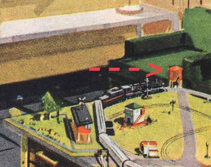
Why would someone place a water tower on a remote corner of the layout instead of in the service yard? The simple answer is probably that there wasn’t room for it between the parallel yard tracks. However, an experienced railroader might see deeper meaning here. It was always a challenge to stop a steam locomotive at a water tank with the tender’s hatch directly under the spout; it was even more challenging while pulling a heavy train, and still more challenging if the tank were located on a curve. At some locations, the task was so daunting that the engineer would have to uncouple the train and move the locomotive alone. On this layout, after #746 has stopped for water, her engineer will face the additional challenge of starting a long, heavy train on a sharp curve going up a steep grade. Toy trains were more than child’s play; they demanded careful planning, close attention, and manual dexterity—some of the reasons they are still fascinating to us in adulthood.
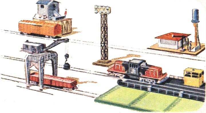
The service yard on this layout had a #350 transfer table to move rolling stock from one parallel track to another. That red gondola under the gantry crane is sitting on a dead-end spur track; it could only have gotten there by riding the transfer table. Apparently, the #625 Lehigh Valley diesel is coming to get the gondola. The artist wants us to imagine that #625 will ride the table to the front track, couple to the gondola, pull it onto the transfer table, ride back, and push the car off onto the middle track. Actually, this wasn’t possible. A #6462 gondola was 10½” long, and Lionel’s model of the GE 44-tonner was 11¾” long. Engine and car couldn’t both fit on the 17½” bed of a #350 transfer table. However, Lionel’s 44-tonner was much too long for the locomotive it was supposed to represent; if #625 had been built to true O scale, it and the gondola would have just fit on the bridge of the transfer table.
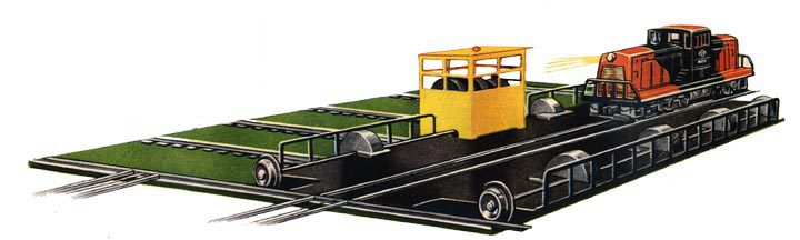
Toy train enthusiasts have wondered if there was a prototype for the #350 accessory. Yes there was, but real railroads didn’t use it the way Lionel catalogs depicted. Transfer tables were most often found at factories that built rolling stock. They were used to move a new car or locomotive out of the erecting bay to the nearest track. Some railroads used them to move engines into repair facilities, but turntables were much more common for this purpose. No real railroad would have used a transfer table to deliver a freight car to a siding. This would have been extravagantly expensive. Any real railroad would have simply built a turnout instead. Ironically, Lionel’s #350 cost the same as a pair of Super “O” remote control switches, and substantially less than a pair of 022 switches.
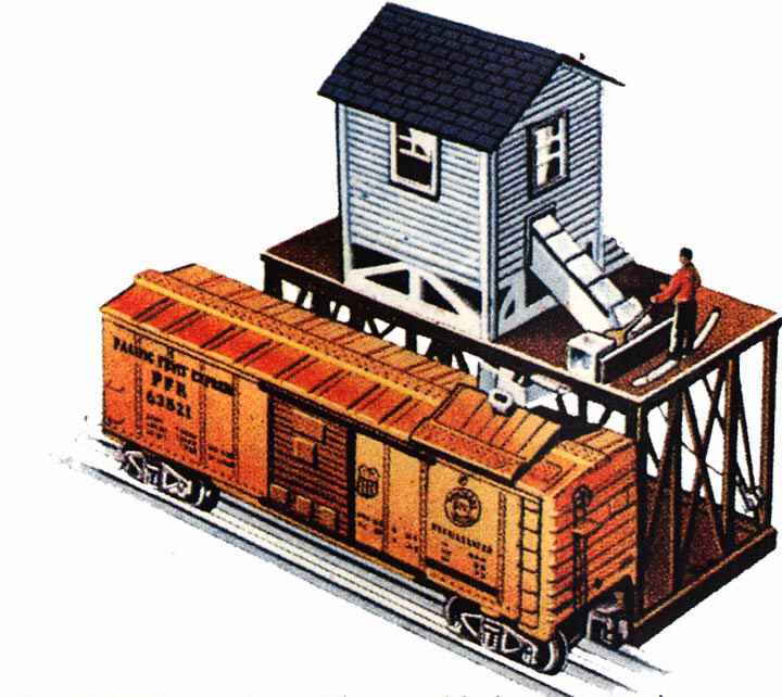
Lionel’s #352 icing station is one of my favorite accessories. It simulated a servicing operation that had been performed on real railroads for over sixty years. Refrigerated railway cars made it possible for us to enjoy the great variety of fresh foods that we have today. Most residents of the northeastern United States had never tasted an orange until it became feasible to ship them by rail from Florida or California. Lionel’s #6352 car was lettered for Pacific Fruit Express, a joint venture of the Southern Pacific and the Union Pacific that operated a vast fleet of reefers from coast to coast. Reefers were cooled by massive blocks of ice that had to be loaded through hatches in the roof. #352 simulated this action with a blue plastic man that pushed clear plastic cubes, one at a time, into a waiting car. When this accessory was introduced by Lionel in 1955, real railroads had already begun using mechanically refrigerated cars (#6672 from 1954 is a model of one). However, in the 1950s PFE still operated tens of thousands of ice-cooled cars, and continued to do so into the 1970s. Thus, the icing station was by no means obsolete when it first appeared in Lionel catalogs.
In both this vignette and in the drawing on the catalog cover, #352 is to the left of #415. In the track plan that Lionel published circa 1960, positions of these two accessories were reversed. #415 was much deeper front-to-back than #352, and would have interfered with the upper-level track if it were installed where these drawings depict it.
Lionel’s #282 gantry crane was a marvel of engineering and a challenge to operate. The cab swiveled; the cable hook was raised and lowered by a winch; and an electromagnet picked up steel objects and dropped them into a waiting gondola. What five-year-old does not beg to play that 25-cent arcade game found in every mall, where you maneuver a steel claw and try to pick up a plush toy animal before time runs out? The gantry crane did all of this, except that it did not demand a supply of quarters.
Service crews worked through the night to get locomotives and cars ready for the next day’s run. Outdoor illumination was essential to get the work done safely, so floodlights like Lionel #195 were common sights at railroad facilities. The example shown here had eight miniature bulbs. If that wasn’t bright enough, you could buy an extra bank of eight lamps that would plug into the first set.
Scene 6: The Control Panel
Electric trains appeal to us for many different reasons. Some of us treasure toy trains because they remind us of family holidays from years gone by. Others prize a model locomotive because it represents a real train that was once an important part of our lives. Some of us use miniature trains to re-create a page from history. Others use a model railroad to express an ideal world that may never have existed.
For young boys growing up in the 1950s, part of the appeal of electric trains was CONTROL. Alternating current, transmitted through the rails to a locomotive, enabled you to regulate a train’s speed, direction and horn/whistle. Other electric circuits made it possible to uncouple cars, load and unload freight, route trains through switches, and operate a variety of signals and animated accessories. You couldn’t achieve a comparable level of control with any other means of propulsion. A clockwork toy, once you wound it, traveled independently until it ran down. Battery-powered toys also went their own way, except for some with hand-held battery packs that were connected to a wire tether.
Young railroaders of the 1950s preferred to sit at a console with all the controls arrayed before them. In this way, they emulated professionals whom they admired and envied. Many of our heroes sat at great panels covered with buttons, levers, dials and flashing lights: railway dispatchers, airline pilots, air traffic controllers, power plant operators, television broadcast engineers; even space-ship commanders, who were still science-fiction characters in 1957 but who became real-life celebrities in the 1960s.
Remote control in the 1950s meant that you could operate a train without directly touching it. Control was accomplished using the same electric current that supplied a train’s energy. Speed was regulated by varying the voltage; direction was changed by interrupting the current with the help of IVES’ sequential reversing unit; horns and whistles were sounded by relays that could detect DC superimposed on the normal AC. Trains were the only toys that could be operated convincingly in this manner. The steel rails that supported a train’s weight also served as conduits for power and control. Transformer-controlled toy cars, boats or airplanes would have been unrealistic because they would have had to drag wires behind them. A few hobbyists flew gas-powered model airplanes by radio control in 1957; but this technology was expensive and called for expert scratchbuilding skills. No one in the 1950s could have dreamed that wireless control of electric trains would become a possibility four decades in the future.
The control panel in Lionel’s 1957 catalog layout was designed for solo operation. One person could run everything from the southwest corner of the table. This showed off remote control to great advantage, since some of the trains and accessories were up to thirteen feet away from the operator. In postwar Lionel Land, mothers and siblings were expected to gather around the table and respond with awe while Junior pushed buttons and pulled levers to make things happen as if by magic.
Do you recognize all of the controls on this panel?
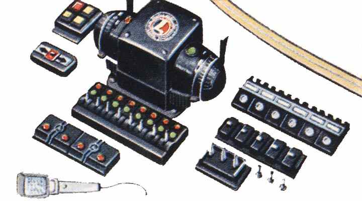
The square console at top left operated the #350 transfer table. Buttons on its left side moved the table forwards and backwards; the indicator light at top right was lit when the bridge was correctly aligned with a track; and the button at lower right energized the track to move the locomotive.
The rectangular control in front of #350C operated the #497 coaling tower. Levers unloaded coal from the dump car, raised or lowered the bucket, and discharged coal from the storage bin.
A 275 watt ZW transformer was the centerpiece of this control panel. Its two large outer handles could each control a train. Each of those circuits included a reverse lever (which simply interrupted current so that the locomotive’s E-unit would cycle) and a whistle control. Two inner levers could each operate one additional train; but no reverse or whistle controls were provided for them. On this layout, the large handles controlled the passenger train pulled by #746 and the freight train hauled by #2341. One of the small levers powered the downgrade on the outer loop; it was set to a lower voltage than the large handle to keep #746 at a safe speed. The other small lever provided fixed voltage for the remote-control turnouts.
Lionel’s ZW was undoubtedly one of the company’s most enduringly popular designs. It was the top-of-the-line transformer from 1948 until the end of the postwar era. In recent years, Lionel LLC has issued a replica of the ZW, which lacks the internal workings (its power now comes from up to four separate bricks) but preserves the transformer’s classic shape. Aside from Santa Fe Warbonnet F3 diesels, the ZW transformer is Lionel’s most instantly recognizable icon. LOTS, the Lionel Operating Train Society, adopted the ZW as it’s club logo.
These catalog drawings didn’t show it, but in a booklet entitled “How to operate Lionel trains and accessories” (circa 1960), Lionel recommended using a 175 watt TW as an auxiliary transformer for this layout. The TW’s variable throttle operated the trolley car, while its fixed-voltage circuits powered the accessories.
In front of the ZW were eight switch controllers. Their design was inspired by the mechanical levers that were once used to operate real turnouts in railroad control towers. Each controller had two light bulbs that indicated the position of it’s switch. As delivered, the green lamp was lit when the switch was set for its through (straight) route; a red lamp glowed if the switch was set for the diverging (curved) route. It was easy to reverse colors by interchanging either the bulbs or the wires.
In front of the switch controllers were two UCS controllers. Lionel’s UCS track section had an electromagnet that could open the couplers on most rolling stock built after 1948; the magnet also actuated operating cars that were equipped with plungers. UCS tracks also had extra rails that supplied current to rolling stock equipped with pickup shoes. Depending on how the rails were energized, this could either uncouple older rolling stock with wire-wound couplers or unload solenoid-powered action cars such as the milk car.
If the 1957 catalog depicted a Super “O” layout, as most enthusiasts believe, then the presence of UCS controllers in this scene was an artist’s mistake. The familiar black plastic box with two orange buttons came only with O gauge and 027 versions of the remote-control track. Uncoupler magnets and unloading power blades were sold separately for Super “O”, and each of these items came with its own, single-button controller. The track plan in “How to operate Lionel trains and accessories” (1960) called for four uncoupler magnets (all in the service yard) and three sets of unloading blades. Thus, there should have been seven 90C pushbuttons on the control panel instead of two UCS controllers.
The handset at the very front of the control panel operated the #465 dispatching station. When you pressed the button and talked into the microphone, your voice was amplified and broadcast from a speaker hidden inside the station.
To the right of the ZW were six #90C pushbuttons. These were spring-loaded, momentary-contact switches that energized an accessory as long as you held the button down. Pushbuttons came with the #118 newsstand with horn, the #138 water tower, the #342 and #345 culvert accessories, the #415 diesel fueling station, and the #3562 barrel car.
In front of the pushbuttons was a row of #364C slide switches, but the artist was inconsistent concerning their quantity. Five switches are shown in this vignette; six are visible on the catalog cover. A #364C operated an accessory continuously until turned off. Six switches were required for this layout: one each came with the #128 animated newsstand, the #362 barrel loader, the #364 log loader, the #397 coal loader, the #464 saw mill, and the #3356 horse car/corral.
The box at the lower right corner of the control panel operated the #282 gantry crane. Its left lever rotated the cab clockwise or counterclockwise; the center lever operated the winch to raise or lower the magnet; the right lever activated the electromagnet, and could be locked in its ON position.
Lionel’s artist was thoroughly familiar with the products depicted on this catalog layout. With the exception of uncouplers already noted, an appropriate controller was shown for every car or accessory that was supposed to come with one. Every switch on the control panel can be accounted for, except the three bat-handle toggle switches at the right front. These were not made by Lionel, but you could buy them in hardware stores for about 35 cents apiece. According to a track plan published in “How to Operate Lionel Trains and Accessories”, toggles were used to divide the ground-level track into electrical blocks; four of them were required. All of the yard tracks were powered by the right handle of the ZW, but you could turn off some of them so that trains could be parked there.
Signals (such as the #253 block signal and #450 signal bridge) needed no switches on the control panel. Instead, they were controlled by #153C track contactors that were activated by the weight of a passing train. Grade crossing accessories (#145 gateman, #140 banjo signal, #252 crossing gate and #445 switch tower) were also activated by #145C track contactors.
Finally, a word about the section of curved track that runs past the control panel. This is our only direct visual evidence that the dream layout was built with Super “O” track. In this vignette, the track is shown with a middle rail that is thinner and less conspicuous than the running rails. Also, there are regularly-spaced specks along the outer rail that suggest ties. This is the only drawing in Lionel’s textbook of model railroading that attempted to show any tie detail.
Conclusion
In six easy lessons, Lionel’s artists and copywriters showed customers how to create a large model railroad system by combining ready-made trains, track and accessories. Everything that you needed to build this dream pike (except for lumber, hardware and paint) was available from Lionel dealers. Next month, we’ll examine a bill of materials and estimate the value of the 1957 catalog layout.

