Layout Wiring Techniques to Cut Downtime
An Excerpt from Automating Your Model Train Layout, 2nd edition, April, 2005
By Don Woodwell, NMRA Model RR Author
When creating a miniature railroad, electricity is routed from a 110-volt AC source (220-volts overseas) plugged into a wall outlet, through a transformer that reduces the voltage, and then to the locomotives, rolling stock, signals, lights, sound systems, and other devices.
Understanding the amount of electrical current drawn by various locomotive motors, lighted passenger cars, accessories, and lighted or animated scenery is important to ensuring the right size wires are selected. Electrical current demands determine the size of the wires needed to distribute electricity needed for flawless operations. This article guides you through the selection of proper wire sizes and connections to enable smooth flow and distribution of electricity to all parts of your layout, and to avoid problems caused by short and open circuits.
Wiring skills involve stringing and routing wires from one point to another, supporting them along the way, and joining them by soldering joints or crimping connectors. With simple skills and some common sense, you should be able to ensure your success and safety. The following tips and techniques should be of great value.
What is Reliable Layout Wiring?
The number of failures in a given period of time is a measurement of reliability. One hundred percent reliability means there are never any failures in the electrical distribution system. Although most of us will always find some glitch in our wiring no matter how well planned and executed, we still should be able to attain reliability in the 90% plus range.
Troubleshooting electrical problems can be a very time consuming effort since there may be many connection points between your transformer and track or accessories. Each connection or wire segment must be isolated and determined to be trouble-free, before moving on to successive points in your distribution wiring. Thus, sticking to a standard way to connect and solder wires and segment electrical distribution with terminal blocks will surely lead to easier troubleshooting in those times when something does go wrong. This is especially true as the number of wiring connection points increases. Even a modest sized layout can have over 100 connection points.
When is a Good Time to Start?
The best time to ensure reliable wiring is when the layout is first constructed. However, if the layout is operating but there are frequent or intermittent electrical problems, then start over to rewire your layout in order to ensure future reliability before expanding it. The time spent rewiring now will surely benefit you later.
If you decide to rewire your layout, I suggest that you adopt your own standards based on certain rules of thumb. For example, practice safe wiring to avoid shocks or burns; use a multi-meter for testing; avoid short circuits; segment your wiring with terminal blocks; use larger wire gauges for multi-motored locos; use small gauge wires for low voltage electronic devices and lighting circuits; use stranded wire when flexibility is needed; use color coded wires, if possible; insulate solder joints with electrical tape or shrink tubing; and, configure your wiring in either Star or Bus mode or a combination of both. The latter consideration is very important if you intend to use either Lionel’s TMCC™ or MTH® DCS™.
What Know-How & Skills are Needed?
A basic understanding of electrical terms is important, but not essential. What everyone should know is that model locomotives generally require more ‘power’ than do caboose lights. Intuitively, a six-motored A-B-A diesel lash up needs more electrical current and higher voltage (the combination of ‘current’ and ‘voltage’ is ‘power’ in electrical terminology) to run at scale speeds than does a single motor yard switcher. Consequently, the wires needed to supply the higher power requirements of mainline diesels or steamers need to be larger than for yard operations. This is especially true if your layout features many grades where the locos exert more pull and thus demand more electricity in order to keep the train’s speed constant.
When asked what skills one needs to wire reliably, my response is “nothing special.” The ability to visualize your wiring project, diagram it, and determinedly set about connecting one wire to another as many times as necessary so that the source (transformer or power pack) is connected to an electrical component is all there is to it.
I have found that the best cure for one’s apprehension about tackling a wiring job is to draw a picture of the wiring. This is usually called a ‘wiring diagram.’ I’ve been wiring train layouts for over 50 years, and always draw a diagram, no matter how simple the job. I always check supplier’s wiring diagrams for accuracy, and if it is not clear, I’ll call the supplier’s technical support desk for clarification.
The ‘art’ of soldering correctly is a skill learned over time since your first attempts to ensure a mechanically and electrically sound splice or connection will be by trial and error. I try to avoid soldering and use solderless terminals in about 90% of my wiring. This is not because I can’t solder, but because I’ve found it to be faster and better to use spade and loop terminals for connections to terminal blocks and butt connectors for splices. Nevertheless, you will need to solder from time to time, so it pays to work on your skills.
Last, the right tools will make a very big difference in how well you test layout electrical circuits and CEMs, trouble shoot problems, strip insulation from wires, attach solderless terminals, and solder. The section on tools is very important for wiring reliably and successfully.
Avoiding Short & Open Circuits
Two other wire features are also important: type of insulation (plastic, paper, cloth), and whether the wire has a stranded or solid metallic conductor.
Modern wiring for toy or model train layouts most often has a thin plastic insulation over the conductors. This is sufficient for low voltage applications, but if a wire’s insulation is broken, a short circuit may occur. This is one of the most common wiring problems.
Short circuits occur whenever two un-insulated or bare electrical conductors touch each other. You may have experienced a short circuit in your home when frayed insulation allowed two lamp cords to touch causing a spark and a loud popping noise and perhaps blowing a fuse or tripping a circuit breaker.
On your train layout, short circuits are not usually so dramatic since the voltages are low. However, there may be a personal safety hazard. The current rise due to a short may cause a wire to heat up enough to burn you even though the voltage is low. If you smell smoke, turn off all power until you can isolate the problem area.
If the short circuit current draw is not sufficient to cause local area heating, then low voltage shorts are often difficult to find especially if you have a lot of wiring. Segmented wiring makes it easier to isolate problems as does adhering to your standard wiring practices and carefully following good installation procedures. Always ensure that insulation is not broken anywhere except at a connection point.
For example, suppose that you use #20 stranded wire for connecting to turnout motors and solenoids. If you strip the wire and wrap it around a screw-down type terminal, it’s possible that one of the tiny wire strands may be dislocated and inadvertently pushed aside it could contact an adjacent wire. This would cause a short circuit and be very hard to detect.
This is one instance where you may wish to either ‘tin’ the end of the stranded wire or crimp a solderless terminal onto it after striping its insulation and twisting the strands together. Tinning the wire means soldering the very tip with just enough solder to keep the strands in permanent contact, but not so much solder that the wire looses its flexibility.
A major problem with short circuits in recent times has been the loss of on-board electronic command control and sound systems due to a derailed train. The newest electronics are very sensitive to rapid current increases resulting from a short circuit. Therefore, a fast acting circuit breaker between your transformer and the track are mandatory especially if the transformer is not one of the newer models designed to work with command control systems.
An open circuit is one in which there is a discontinuity along a wiring path over which electricity does not flow. Open circuits do not have safety hazards associated with them. Whatever is connected to the opened circuit just doesn’t work. Trace your wiring from your source to the component and test it one segment at a time. A wiring diagram will come in handy at such times.
Polarity Consciousness
When working with AC, it usually does not matter whether you connect one or the other power wire to an accessory even though it is normal to connect a transformer common to a side rail and lettered post to the center rail. However, some electronic modules used as detectors or timers may require that you adhere to certain connection standards or the device will not work. You don’t have a choice in such cases but to follow the supplier’s rules. I’ve found that sticking to a common standard is a sure formula for success. Colored coded wires, solderless connectors, and segmented wiring make it much easier to ensure that polarity is followed and to trace a wire back to its source.
What Tools are Required?
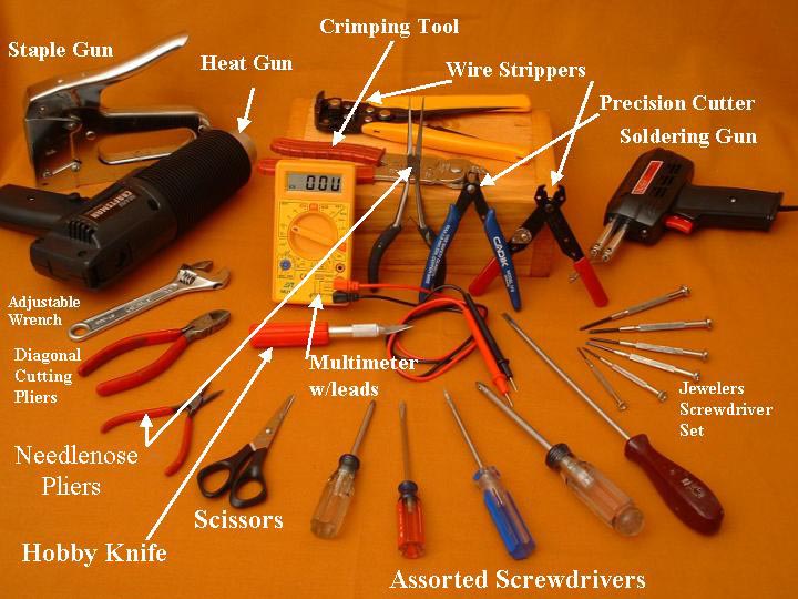
Tools for Reliable Wiring
(1) A multimeter is the first and most important tool. This instrument measures electrical properties such as current, resistance, and voltage. Small multimeters are available from electronic stores for under $20. Care for it properly, and it will last a long time.
You can use the meter for both voltage and resistance measurements. If you have wired a circuit, but the device doesn’t operate, you can test for voltage from the transformer outward. Place the meter probes on each connection point and watch for volts on either the swinging needle (analog meter) or digits (digital meter). If your trains are not running smoothly, you can test the track voltage at different points to determine if voltage is lost either due to track or connection resistance.
(2) A wire cutter and stripper may be a combination tool or two separate tools. I use both, but prefer a small, very sharp precision wire cutter.
(3) Screw drivers in assorted sizes and blade types are always needed. Optionally, I use a rechargeable, handheld power screwdriver. This makes many wiring jobs go faster especially if you are opening and tightening many terminal blocks’ screws.
(4) A soldering iron or gun is necessary for joining wires where terminal blocks and solderless terminals are not feasible. A 75-watt iron or gun will ensure that you have enough capacity to sufficiently heat larger gauge wires so that the solder flows through the joint to ensure a solid electrical connection. This is another key to reliable wiring. A great solder connection is one that is shiny and bright, not dull and pocked. Be sure to use a ‘heatsink’ when soldering wires to electronic components to prevent overheating. A common heatsink is a small, spring-loaded, aluminum clamp that is clipped onto a component’s lead to absorb soldering heat. Electronic stores sell them with soldering irons.
Whenever you solder wires, remove only enough insulation with your wire stripper to allow the clean, bare conductors to be twisted together so they have mechanical strength, and then solder them together. When the joint cools, cover the soldered joint with either electrical tape or shrink tubing. The latter shrinks when heat is applied. You can simply use the heat of a match or heat gun held underneath the tubing. Canned liquid tape may be painted on the splice/joint and is particularly useful when electrical tape is too stiff.
(6) Staple gun (optional) – stapling your wires every foot or so under your layout surface helps to organize your wiring runs, looks better than droopy wires, and adds to reliability because there’s less chance to snag them when working underneath your layout.
What Materials are Necessary?

Materials for Reliable Wiring
(1) Wires in different sizes and types depend on your layout’s electricity requirements and length of wire runs. Large O-gauge layouts with scale sized engines pulling long trains on several hundred feet of mainline track, 12-gauge wire or heavier may be needed to not only handle the heavy power demands but also reduce the voltage loss due to the wire’s internal resistance. With big power needs, track connections every 3 feet or so may also be necessary.
(2) Terminal blocks or barrier strips with 2 to 8 paired terminals are important in order to segment your wiring distribution. I’ve found that isolating transformers from any electrical device is a smart thing to do. All my main power leads from multiple transformers are connected to terminal blocks under the layout. All distribution wiring terminates in these blocks.
Segmented Wiring: I run a 16-18 gauge 2-wire conductor from two transformer terminals to a block. From that point, all my tracks or accessories are connected. At an 8-position block, I connect one of the transformer leads then link each of the positions with a jumper wire so that now I have eight points to which I can connect some track or device. The other transformer lead is then connected to a second block with jumpers to give me eight appearances of that lead.

Segmented Terminal Block Wiring
By organizing electricity distribution by segment, maintenance, trouble-shooting, and changes are much easier to accomplish.
Since no devices are attached directly to the transformer posts, reliability is enhanced because you have eight screw terminals from which to draw power, not just one. This helps to ensure that all power connectors are screwed down tight, make good electrical connection, and look much better. If more than eight connection points are required for either lead, jump from the first terminal block to a second one where there may be two, four, six, or eight additional screw posts. Such segmenting organization makes troubleshooting easier.
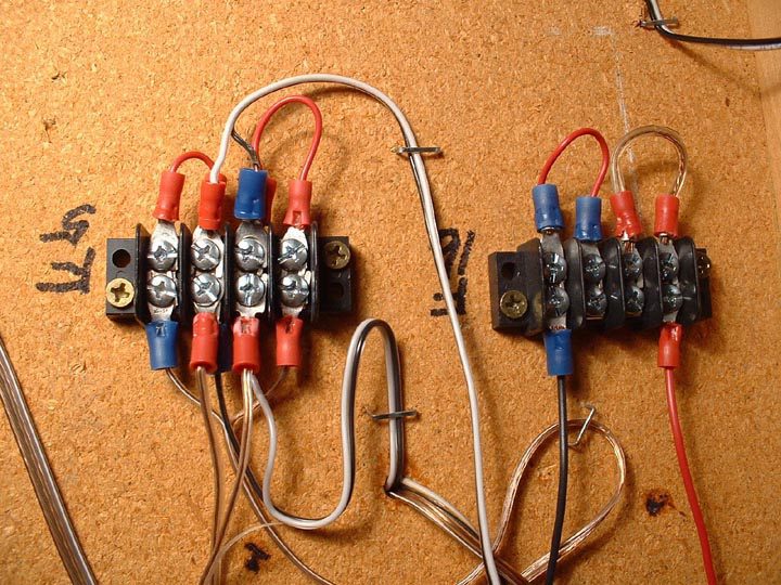
Segmented Terminal Block Wiring
The left terminal block is a distributed DC power point, and various accessories like a highway flasher, station stopper module, & others use the right terminal block.
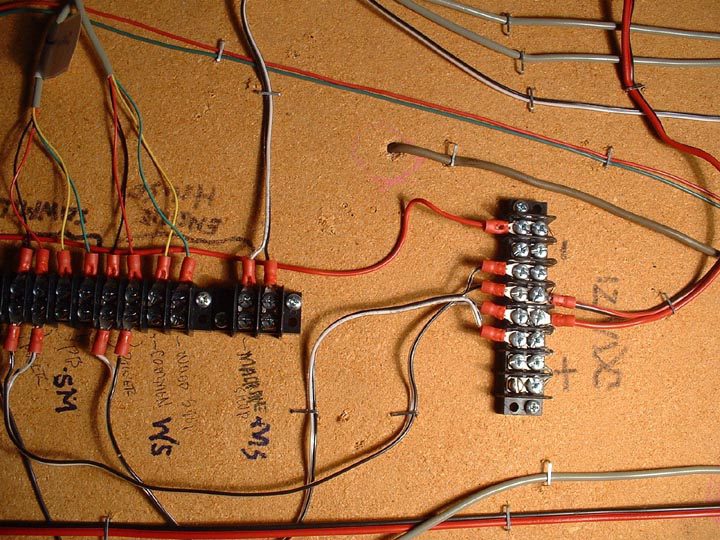
Segmented Terminal Block Wiring
This terminal block cluster connects the master control panel to the layout’s switches (turnouts

Segmented Terminal Block Wiring for Sound Systems
Wires above the terminal blocks lead to the power sources and central control panel, and wires below come from the individual soundboards located in the engine house, sawmill, and others.
(3) Solderless terminals are aluminum pieces shaped into butt, spade, and loop connectors each with plastic insulating sleeves, and sized for the wires to which they will be attached. Crimp them onto the ends of a wire using the crimping tool mentioned above.
Butt connectors are for splicing two wire ends together. This is often easier than soldering. If properly crimped, the wires will not pull out of the connector. After each crimp, pull on the wire and terminal to ensure they are firmly connected. If they are, you can be sure they will reliably conduct electricity.
Use either spade or loop connectors for reliable wiring and for connecting a wire to a terminal block. Just looping a bare wire around a terminal block screw and tightening it will eventually cause problems with poor contact between the wire and the screw, and corrosion that causes high resistance. Further, if using stranded wire, a loose strand may accidentally touch a neighboring terminal thereby causing a short circuit. Since these small copper strands are hard to see, such a problem is hard to detect.
(4) Shrink tubing is used to insulate solder joints as mentioned above. It’s available in electronics stores in both long and short lengths and various diameters to accommodate all wiring gauges. Slip a length of tubing over a soldered joint and heat the tubing with a lighted match or heat gun to shrink it over the joint.
(5) Electrical tape may also be used to insulate solder joints, but I only use it for large joints with #16 wire and up. If used to insulate small gauge wiring joints, the tape’s inherent stiffness causes it to unwind from the joint that could bare a conductor causing a potential problem.
(6) Liquid Electrical Tape works very well on most model railroading low voltage connections that have been soldered. It is especially useful for the small gauge joints. If a joint is subject to abrasion, however, a tape or a crimped connection may be a better insulator since it is possible to inadvertently scrap off the coating thus exposing the conductor.
(7) Cable ties are plastic straps for securing bundles of wires. You loop it though its’ lock and snap it in place to snug the wires together.
(8) Velcro Strips: Each box contains five feet of industrial strength Velcro. Cut it to whatever length you need, peel off the backing from the loop tape and stick it to the underside of the layout. Leave the backing attached to the other strip, trap the wires between the two Velcro pieces, and press together for a very satisfactory wire management solution.
How to draw a wiring diagram:
• Use 1/4″ quad-ruled paper
• Show the purpose of the wire
• High current (12-16 gauge) – locomotives, lighted passenger cars
• Medium current (18-22 gauge) – operating accessories, signals with light bulbs, some layout lights
• Low current (24-32 gauge) – electronics, LED signals, low level background lighting
• Show the beginning and ending point of a single wire
• Color code the wires by size or use
• Show terminal blocks and connections to power sources and devices
• Make notes about the types of connectors required
Rely on your diagram when stringing and connecting your wires, and follow your diagrams and the previous guidelines for cutting, stripping, crimping or soldering wires in order to ensure neat and reliable layout wiring.
Trouble-free train operations will more than justify the extra time that you spent ensuring that your wiring is as reliable as you can make it. Rewiring troublesome circuits wastes time and is downright frustrating.
If any problems do occur with a properly wired layout, it will be much easier to find them. Segmented wiring not only reduces problems but also simplifies future wiring changes. The whole idea is to spend your time running your trains, not constantly lying on your back under your layout tracing wiring problems.