Flyerizing Thomas; Part 2: Thomas is Ready to “GO FLYER!” He has Choo-Choo sounds, smoke and LEDs!
By Carl Giambrone (TCA 83-19674) and John Halajko (TCA 84-20653)
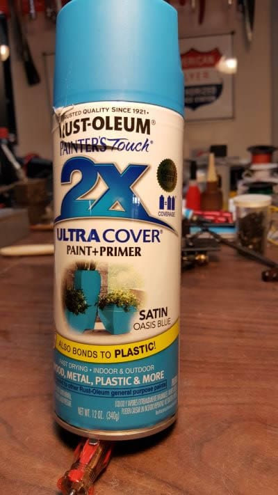
This article is a continuation of our earlier Flyerizing Thomas, Part 1 eTrain posting that featured an American Flyer Thomas made from a Schilling whistle and a Flyer Atlantic. In our Part 1 article we emphasized making no changes to the original American Flyer piece so that it can be returned to its original condition. We take no such liberty in Part 2 which will show what could be possible. Lionel has not yet extended into its American Flyer Line an S-Gauge Thomas the Tank Engine. We look forward to enjoying the future memories. For those of us who just cannot wait, the Schylling whistle may now be in stock at your local hobby store. It makes a great looking Thomas. Nicholas Smith Trains, Broomall, PA had lots of in stock. For details on the Schilling whistle please see Flyerizing Thomas, Part 1.
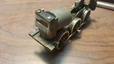
We promised that Flyerizing Thomas, Part 2 would show the details of the shell surgery along with how to use a six-wheel drive. We make good on this promise by creating a nonreturnable-to-factory condition, six-wheel drive Flyer Hudson or Pacific into a real crowd pleaser. Many thanks to Steve Stevens for providing a Flyer six-wheel chassis and motor along with the tender and wiring essentials at reasonable costs. He has lots of Flyer parts for this and other projects. He can be reached at [email protected].
The details to customize the top part of the Schilling Whistle Shell are covered in Part 2 while the custom painting and final assembly are covered in Part 3. Together Parts 2 and 3 form a ten Step Process to do the transformation. The reader can combine Parts1 and 2 to use an Atlantic Chassis if they so desire. Part 4 of this Article will discuss the modification that should be taken if a Pull-Mor wheel is used.
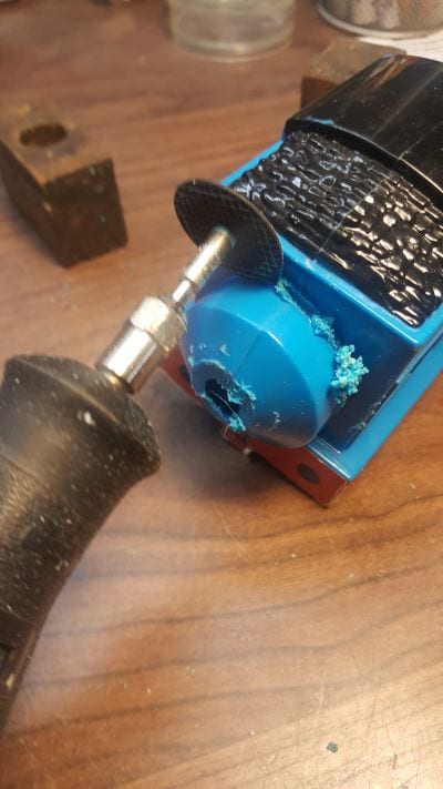
We assume that the reader is familiar with the safe use of the Dremel tool. We add the caution of using safety goggles and gloves. Remember that you only have one set of eyes. There are no spares.
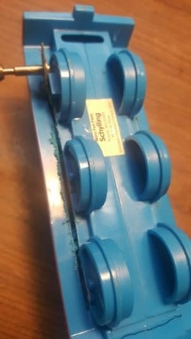
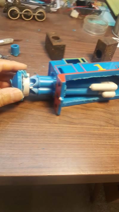
Step 1: Cut out the plastic wheels.
You will need to make four cuts to the bottom of the shell as shown below to remove the wheels.
Make two cuts along the wheels. Make the rear cut as close to the mouthpiece as possible.
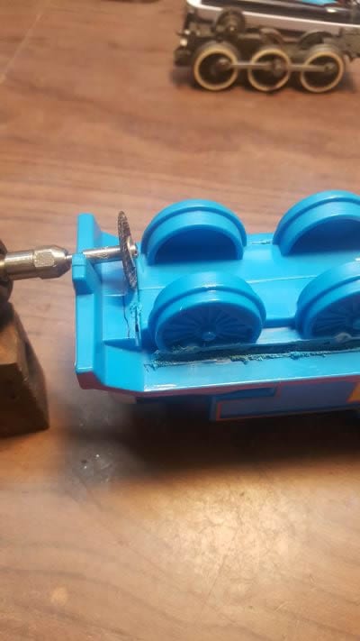
Making the front cut as shown. You will need to use a Dremel bit at the front corners. Remove the wheel assembly (which makes a great gondola load when painted flat black!)
Step 2: Remove the whistle and mouthpiece.
Carl’s enthusiasm was a little too much when he removed the mouthpiece from the air whistle. It was not required. Save the whistle for the younger guys or just give it away for a gift. It still works without the shell.
Take care when removing the mouthpiece neck.
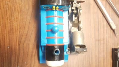
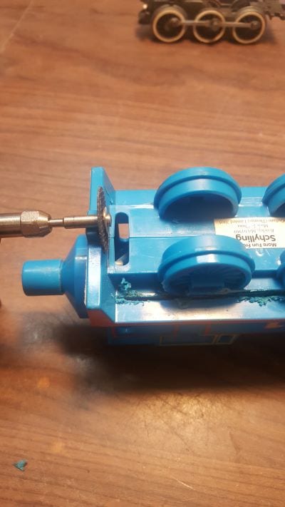
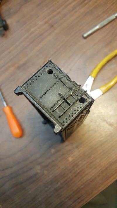
Step 3: Remove the interfering smoke unit as required.
Our Flyer chassis featured the Flyer chuff mechanism and attached smoke unit which needed to be modified to fit into the Thomas shell. Alas, the Schilling whistle will not take the full chuff/smoke assembly. Carl’s cut is shown above removing the smoke unit.
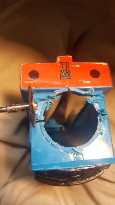
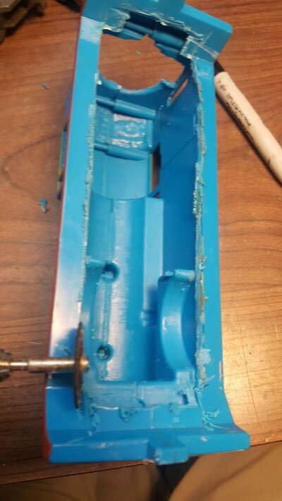
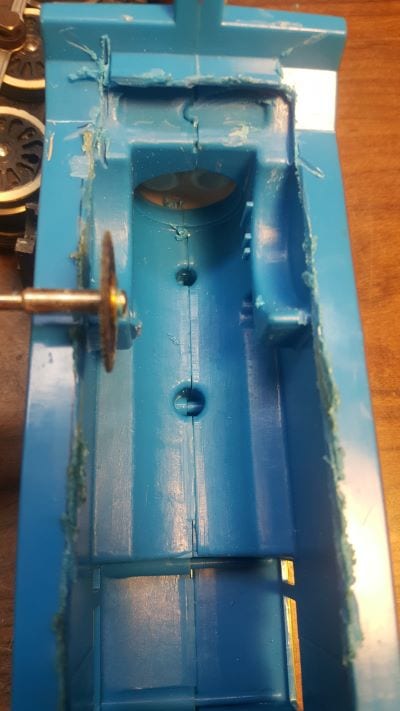
Step 4: Remove material from the shell as required.
We are now at the hardest part of the modification. If you mess up remember that a little BONDO goes a long-long way. Our Flyer chassis started with a Flyer chuff/smoke mechanism which needed to be modified to fit into the Thomas shell. You will now need to repeatedly cut a little with the Dremel and then test fit the motor assembly removing a little bit of interference at a time. Carl chose to remove the motor to make it a bit easier to test fit.
Remember, it is better to test fit twice and cut once.
Repeatedly test fit the chassis to assure that all interferences are removed.
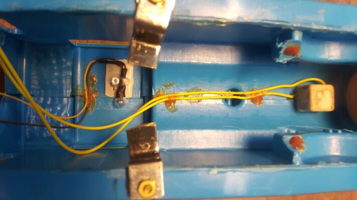
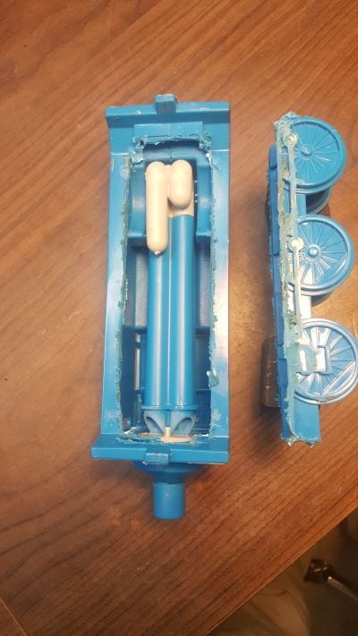
Step 5: Fabricate mounting hardware.
Our Flyer chassis featured the Flyer chuff/smoke mechanism which needed to be modified to fit into the Thomas shell. Carl chose to keep the remaining material to add weight to the engine front to prevent the wheels from riding up the rail on curves. It is a good idea to add some lead weight to the front as we discovered with the Atlantic version when using a Pull-Mor Wheel and uneven track. We will address this issue in our Part 4 article.
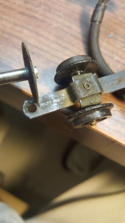
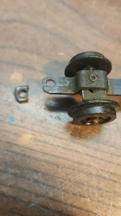
The chassis front is secured to the shell with two screws drilled to the proper position. The middle is supported by two metal tab brackets and cut away shell tabs. Shell tabs were reworked to the proper height to prevent the chassis from moving up into the shell too much. Take your time here and test fit removing a little plastic at a time. When finished the bottom looks like below. The material removed from the shell back may not be necessary.
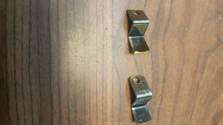
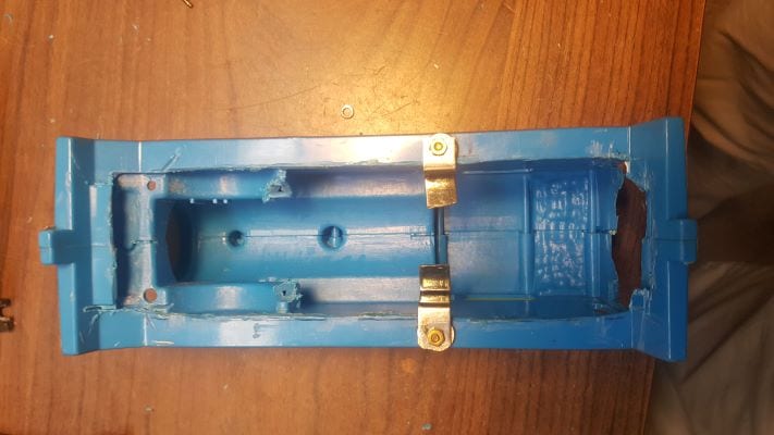
Two metal tab brackets screwed into cutaway shelf tab.
Note the arrows showing the removal of plastic to form a shelf to prevent the chassis from riding up into the shell.
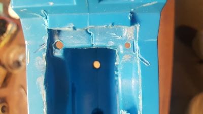
Rework the front to form a mounting shelf for the chassis and drill two screw holes for the front of the chassis frame.
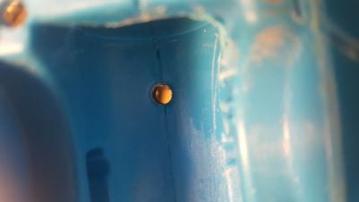
Smoke Hole in shell and Bachmann smoke unit.
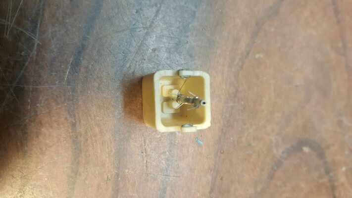
Step 6: Add smoke unit mounting hole and LED lights.
The addition of LED lighting and a Bachman smoke unit is a Giambrone Special. He has done this to several of his Flyer pieces. Open a hole in the stack to glue the smoke unit to the shell.
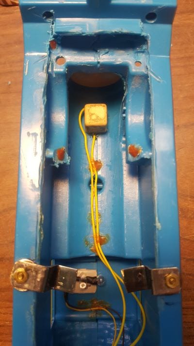
Drill two screw holes for LED lights, install smoke unit with leads and cab light. When done the shell underside looks like above. You can use hot glue or any epoxy resin to rework shelf tabs to hold the chassis
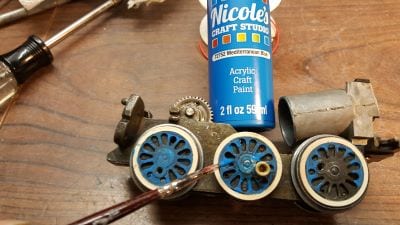
Step 7: Make modifications to drawbar and paint the six-wheel drive train.
You can paint the drive wheels to give Thomas that Royal Blue Appearance. At this point, assemble the shell to the chassis and motor to determine drawbar length. Ours was a bit too long.
Step 8: add LEDs to tender and then paint your project.
Carl chose to make this a Super-Duper Thomas by adding LEDs to both the engine and tender. He chose to have a set of wheels under the cab, and re-lettered the tender.
We will end this part of the project and continue the assembly and custom painting in Part 3 which will be published in the Fall 2020 TCA e*Train. Fear not, we will continue the Step Numbering System where we left off at Step 8.
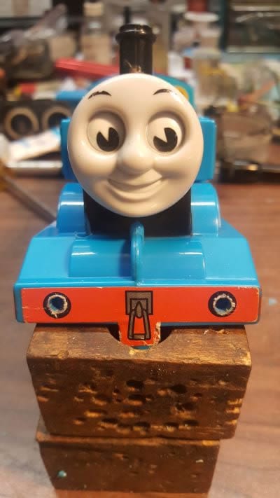
Here is a preview of what the final project looks like.