Detecting Your Trains & Separating them with Blocks
By Don Woodwell
(excerpted from Automating Your Model Train Layout, 2nd Edition)
The invention of the basic track circuit for operating railroads in 1872 by Dr. William Robinson enables trains to automatically operate signals by completing an electrical path between the loco/car wheels and the rails. The train completes a battery circuit by electrically bridging across the rails and, thereby, activating a relay. The relay contacts then become the input to a signaling system stating that this section of track (a “block”) is occupied.
What the signal system does with this information is wholly dependent upon the railroad’s operating rules. Overly simplified, if a block is occupied, the signal aspects at either end of the section should be “Stop” so that an engineer in an approaching train knows that he must not enter the occupied block.
Model railroaders define detection as the ability to know the location on a layout of a locomotive or piece of rolling stock even when that equipment is hidden from view. For example, operating two trains on one loop of track requires blocks so that one train may stop before it runs into the one ahead of it. Knowing where each train is located is the purpose of detectors both mechanical and electrical as described in Part I.
Blocks are variable track sections whose lengths are determined by several factors including train length, track purpose, electrical power requirements for operations, and number of trains running on a main or branch line. These will be covered here in Part II.
Throughout this article, references will be made to specific installations and usage examples on my NC-Lines & Traction high-rail layout in order to illustrate automatic applications of detectors, blocks, and commercial electronic modules. The latter – CEM for short – are any of the varied off-the-shelf electronic modules designed and built for specific control applications such as sound reproduction, train detection, lighting trains with constant voltage, animation and lighting sequence timing, signaling control, among many others. Although NC Lines is 3-rail, the following examples also apply to 2-rail layouts. Any unique differences will pointed out and discussed.
Detectors
In the modeling world, we do the same thing with an insulated track section (ITS) as Dr. Robinson does with his track circuits. One of the two outside common rails on 3-rail track requires isolation from the other in a block. When a metal wheel and axle set bridges the two rails, it completes a circuit that may activate signals, other operating accessories, or relays as shown.
Early forms of electrical detection relied on large relays with sensitive coils. Power was routed to the track through the relay coil, and when a locomotive was in the section of track wired to the coil, the relay would activate. This system worked effectively for the ‘O’ Scale and larger equipment in use in those days, but as HO scale became popular, with its smaller motors and much lower current draw, the series relay form of detection lost favor.
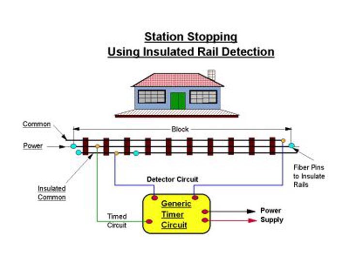
An insulated track section may be used to activate a Timer circuit for stopping at a way station.
Another early form of detection was the track switch, a mechanical device used extensively by Lionel, American Flyer and other tinplate train manufacturers.
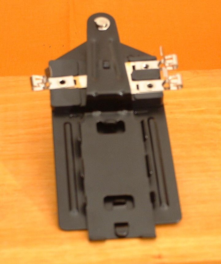
It consisted of a spring-loaded contact assembly that was activated by the weight of the passing train. Although adequate for the simple signal and crossing gate needs of those tinplate layouts, they were not very stable, and are not practical for a layout where the track is fixed to the roadbed. In recent years, Lionel and MTH in particular developed an infrared detector to replace the mechanical devices.
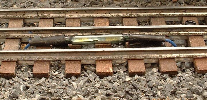
Magnetic reed switches are reliable detectors, but they often require modifying locomotives or rolling stock. In practice, when a permanent magnet mounted on a locomotive, for example, passes over a reed switch between the rails, the magnetic attraction momentarily pulls two metal ‘reeds’ together completing an electrical circuit. The metal reeds are housed in a glass tube with leads on each end.
One application for this detector type is stopping a train at a station. The permanent magnet, however, must come within 1/4″ or so of the reed. This means that you must find a location on your engine where you can mount the magnet so that it pulls on the metal reeds. Any locomotive that is required to stop at the station must have a magnet attached to it.
About the same time that 2-rail DC powered HO scale layouts started to replace the larger scales, transistors were invented, and these led to the development of true electronic detectors. The Twin-T circuit, designed by Lynn Westcott was simple, sensitive and effective, and it found immediate favor with modelers. The Twin-T circuit was sensitive enough that rolling stock could now be detected if a resistor was placed across the insulated wheel sets.
Detecting current flow caused by the presence of a locomotive or lighted car within a block is enabled with modern electronic circuits called current sensing detectors (CSD). Detection only occurs, however, if something draws current. Rolling stock with plastic wheels would not, however, be detected. A block must be longer than any train that runs through it so that a lighted caboose would be detected at the rear of the train. When it is detected, then the block is no longer occupied.
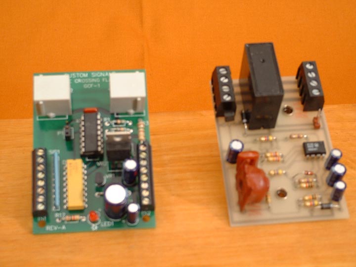
Ideally, CSDs should be electrically isolated from track power so that it does not take power from the track nor should it be affected by short circuits. DALLEE Electronics accomplishes this by having one wire to the track section physically pass through a hole in the detection coil of its TRAK-DT device. See Figure 4.
Current flowing in the wire due to a train’s presence induces current in the detection coil that activates a relay of the TRACK-DT. The relay output can be applied to a signaling or other electronic application.
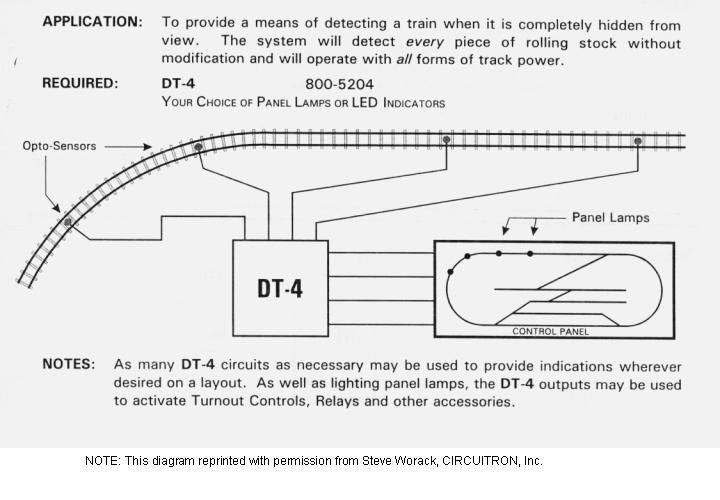
After Iow cost integrated circuits (ICs) — with hundreds and sometimes thousands of transistors on one chip — were developed, a number of manufacturers started utilizing this new technology to provide sophisticated detection for model railroads. CIRCUITRON pioneered the use of integrated circuits combined with tiny optical sensors for optical-electronic detection (OED) in any scale. ICs have also been used to replace the discrete transistors of the Twin-T circuit, and they offer greater sensitivity and more stability.
NC-Lines uses both the ITS and infrared detection (IRD) method so as to get the most flexibility. However, there’s another reason for choosing the IRD device. If an insulated track section is already used at the same location to activate a grade crossing signal, you may not want both signals operating at the same time. Therefore, you need an alternate detection means. The IRD or OED device also may be better if you use 3-rail sectional track with metal ties. Work can be saved since insulating a section means bending track clips, lifting rails, sliding insulators between the rail and the tie, and then pressing the track clips down.
For most 2-rail applications, the opto-electronic detectors are the easiest to install, particularly when the track is already in place and wired. A typical OED by CIRCUITRON is only 0.18″ (4.6 mm) in diameter, and easily fit between the ties in HO scale. As such, it is unnecessary to remove or alter any existing track, and in most cases, no loss of performance will result even if the Opto-Electronic detectors are covered with a thin layer of ballast. The associated circuitry is highly sophisticated and sensitive and will operate properly under extremely low levels of room light. These OED circuits contain sensitivity adjustment controls to adapt them to your existing room light.
The current-sensing type of detector is the most practical when you desire to operate under varying lighting conditions or in total darkness. The CSD circuits may be less costly, per block, than the OED; however, wiring is more complicated and each piece of rolling stock will need to be modified in order for the electronics to detect it. Metal wheel and axle sets must be installed, and resistors or resistance paint will have to be applied across the axle insulator if you want to detect each piece of rolling stock. These added costs should be considered when comparing systems.
Installation requires an air gap in one rail at both ends of a block. Pass the feeder wire through a hole in a component mounted on the 1-1/4″ square circuit board, solder it to the rail between the gaps, and connect the board to 12-16 volts AC or DC. A separate power supply isn’t required. A relay energizes when a train is detected enabling the Detective’s contacts to be used to control signals, panel lights, or other accessories.
Detector Placement
Train detection is important for many reasons other than multiple train operation. For example, both NC-Lines (the railroad) and NC Traction (interurban trolleys) use detectors for signaling. Detectors that tell where a train or trolley is located also control signal aspects. Detector output also controls block access so that mainline signals are coordinated with block occupancy. Train location detectors may be used for other applications such as activating accessories, stationary sound, grade crossing signals, or for automatic switch and signal control.
Blocks
Prototype railroads break their mainlines into blocks in order to allow multiple trains to run safely on the same track. Block signals inform the train crew of the upcoming blocks’ status and whether or not another train occupies them. The crew takes action as dictated by the signals. They may, for instance, continue at an allowable speed or reduced speed due to the blocks’ status. In real life, the train engineer can speed up or slow down his train as necessary.
It’s the purpose of the block occupancy detector to determine if a following train must be slowed or stopped in a preceding block to avoid a rear end collision on a subsequent block. Thus, go-no go decisions are automatic based upon train location.
The key to stopping a following train is to place occupancy detectors at the beginning of a block so that the following train slows down two blocks behind the first train, and stops in the immediately preceding block. This blocking practice should enable the model railroad operator to maintain spacing between his trains. Compared to prototype railroads, model trains stop in a very short distance, therefore a block at least equal to one train length is sufficient distance for the following train to stop.
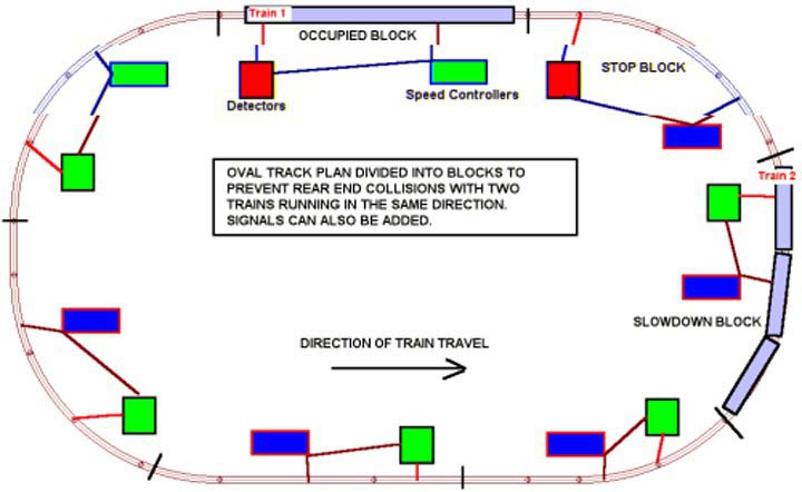
Slowing in one block or stopping in the next one ensures that the lead train is far enough in advance to avoid a collision. When the lead train reaches a location further along its route, its position is detected and the following train is allowed to resume normal speed.
Space-interval blocking such as described requires no signaling only control of track power. Nevertheless, adding signals will increase your layout’s visual interest. Model railroads rarely need prototypical signaling systems, but the addition of signal components adds a tremendous amount of realism, and changing signal lights impress viewers as trains pass by.
Track blocks also may be in yard areas or passing sidings. These two types of blocks are static, and they are either ‘on’ or ‘off’ as an operator controls them. Mainline blocks are dynamic, on the other hand, if there is more than one train operating on the mainline. The state of a dynamic block is controlled by train location.
Passing Sidings
A different way to run two or more trains on a mainline is to create passing sidings each of which is a separate block. The number of passing sidings is one less than the number of trains running on the mainline . One or more trains can be parked in un-powered sidings while another train runs around the mainline.
Let’s suppose, for example, you want each of two trains to alternate access to the mainline and stop in a siding. When one train stops, the other train departs, makes one mainline run, then returns to the siding and stops. Control of this alternating mainline use is dependent upon a stop circuit. Power would be cut in the passing siding block when the train’s presence is detected within the siding. After a short time delay to allow the moving train to fully stop, power is applied to the second passing siding block and the other train departs. Such block control is simple to create and is a basic form of automation.
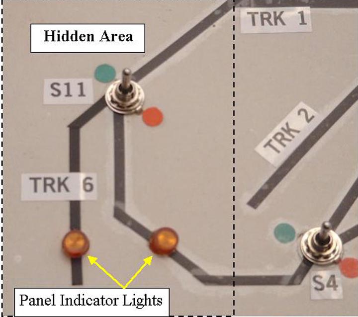
Block Indicator Lights
Indicator lights on the layout control panel activated by detectors make it easy to spot both rolling stock and complete trains positioned on hidden track blocks like staging tracks or sidings. On NC-Lines, two end loops are hidden by a mountain and city, and one siding is hidden under the mountain. Each location only requires a short piece of insulated track section to detect the presence of a passing train or stored rolling stock. I mounted three amber panel Indicator lights on my control panel’s track diagram corresponding to the detector’s locations. A current sensing detector could also be used, but not an opto-electronic detector since each track location is in the dark.
Summary
Detector circuits are extremely important for sensing train locations and then taking some action. The action may be to control signaling, slow or stop a train, activate grade crossing gates and lights, or start up a rail side accessory. Blocks are sections of track that may or may not be powered depending on train activity on the mainline or in the yard. Both detectors and blocks are usually part of any model railroad whether in conventional, cab, or command control.