American Flyer Early Mystery Electric Engine

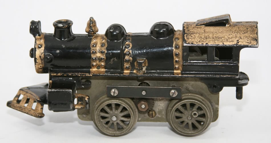
Two sides of the mystery engine (click any picture for larger view)
By Leon Sweet
My first thought on seeing this engine was that someone had performed a lot of modifications to it. A friend had brought it to the December 2013 Great Midwest Train Show in Chicago to show it to me and ask me about it, as he had recently picked it up at a flea market and wanted to resell it.
I knew that it was of the style of the earliest Flyer electric steam engines from 1918, but the presence of round/tube brushes had to be a modification, as to my knowledge American Flyer had not started using round/tube brushes until about 1925 and this engine was clearly from the 1918 era. However, as I looked at the engine closer, I began to see other features that did not add up to what I knew about these engines, but just could not remember all of the details of my own similar era engines. I offered a low price for it as I was just unsure about it. When it was refused, I asked him to hold it for a few weeks and told him I would bring my engines of the same era to the next show.


Upon arriving home that day, I promptly went to the train cavern to hunt through the musty shelves to find my other two engines of a similar era. In particular I went to one engine (shown in the photos above for comparison) because I knew it had similar early cast iron / machined wheels. I found the engine and looked at the side with the pinion gear, and paled, as I knew what I saw earlier in the day had to be original. I ran upstairs and sent an email to my friend asking him to bring the engine to the Midwest Division Christmas meet, a few weeks later. He said he would.
So what did I see on my engine to know that the engine my friend had shown me was original? It was the cutout around the pinion gear. This early odd engine features a frame cutout that is just big enough for the pinion gear to fit through the frame, where the other early engine I have features a larger cutout in the frame that exposes much of the armature. I realized that one cannot change the larger frame cutout once it is done, so the odd engine with this small frame cutout had to be at least original to that feature, which was very odd.

So at the Midwest Division Christmas TCA show, I took along my other two engines and showed them to my friend and we discussed the engine he had. We discussed that American Flyer had first introduced the electric powered engines in 1918 and apparently was making a number of changes during the early production and that his engine represented an early production motor that had some features that were not mass produced. I offered a fair price for the engine and he accepted.
The one thing I never let on to my friend, is how exciting this engine was to me. Round/Tube brushes on an early engine? Were they original? Was this some sort of engineering / production sample? I had to get home and take the engine apart and make a full comparison of the two motors.
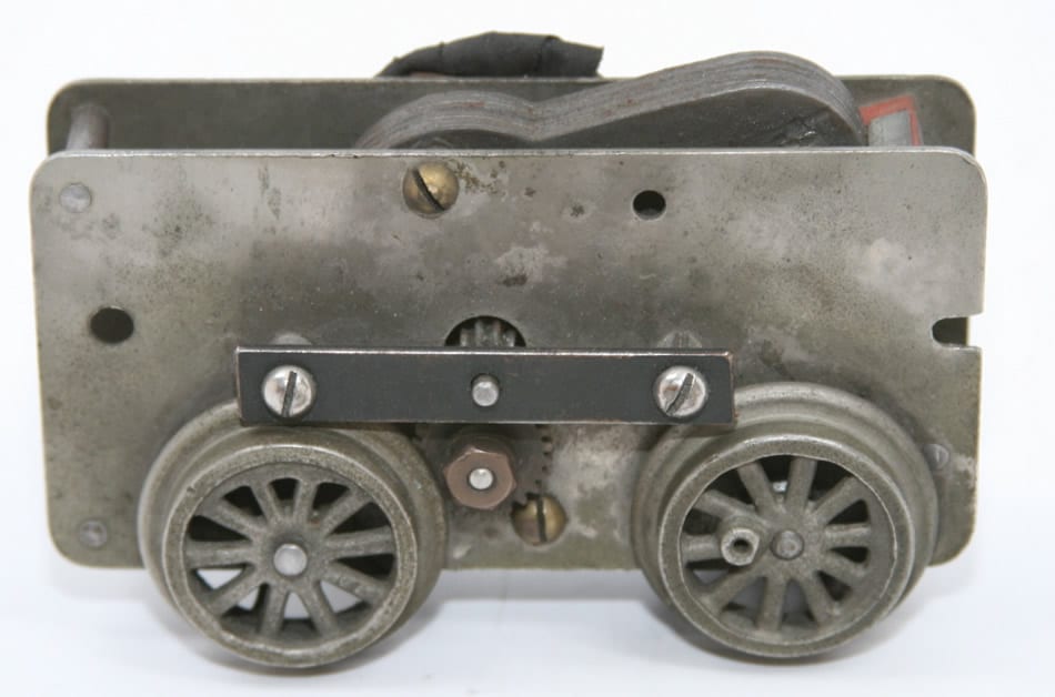
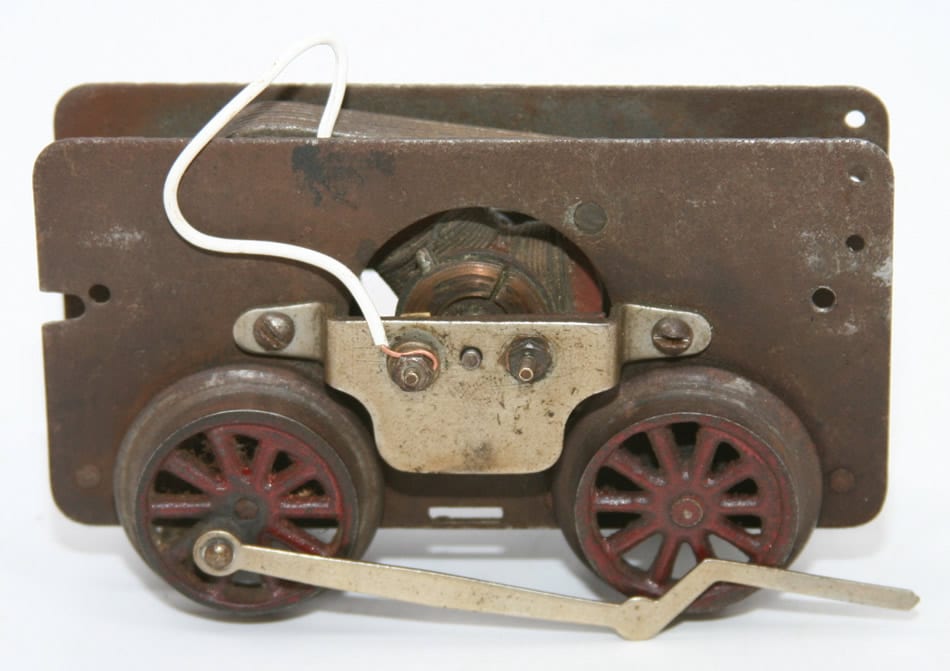
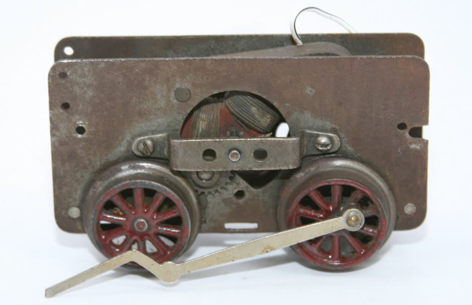
Upon taking the motor out of the cab and comparing it to the later production 1918 motor, there were several things I noted about the older odd engine.
1) The frame cutout on the pinion gear side was just large enough for the gear, as opposed to the later production 1918 motor, which has a large frame cutout that exposes much of the armature.
2) Round/Tube brushes. Prior to seeing this engine, I was not aware of American Flyer using round/tube brushes on engines prior to 1925. I will detail my thoughts about these brushes later.
3) The brackets that hold the armature in place are very crude and are made out of bar-stock steel that is cut at the ends, with spacers holding them out from the frame. Although some have suggested that these may be in fact kit-bashed, they are not. I attribute these crude armature brackets to be original, simply because their attaching nut/bolts are spaced differently than the screw holes that hold on the later production 1918 motor and there are no extra holes in the frame. Additionally, this motor has one very different feature than the later production motor, in that there is a single nut and bolt holding the two sides of the armature brackets. The long bolt runs through the one side of the bracket, through the spacer, through the frame, through another spacer between the two frame halves, through the other side of the frame, through another spacer, through the other armature bracket, and then is held in place with a nut.
4) The placement of the armature brackets near the front wheels is not quite perfect and the spacers holding the brackets out from the frame had to be ground to allow clearance for the wheel flange. The later production motors feature a one-piece armature bracket that is designed for no obstructions with the wheel flanges.
5) The main field in the motor can be removed and is held in place with nut and bolts, similar to the armature brackets, in that there is a long bolt running from half of the frame, through a spacer, through the field, through another spacer, through the other half of the frame and held in place with a nut. The later production motor features a field that is riveted in place and is not removable.
6) The idler gear is held on by a nut at the end of its shaft. Additionally, the idler gear is mounted to the frame in a different position than on the later motor. The center shaft is nearly directly below the center shaft of the armature, whereas on the later motors the idler gear is centered more forward and up from the location on the earlier engine.
7) The wheels on the early engine are machined differently than on the later engine. I had noted that the flanges were thicker and more rounded, when looking from the top down, but have also noted that the diameter of the wheels is 1/32 inch greater than the later motors, with the difference being attributed to the size of the flanges (ie the main diameter of the wheel without the flanges is the same).
8) The main field is differently sized in thickness and shape as compared to the later production 1918 motor and has different attachment points.
9) The two halves of the frame feature some of the same rivet attachment points as the later production 1918 motor, but has some different rivet attachment points. Specifically, the rear rivet is mounted approximately ¾ inch from the bottom of the frame on the odd motor and is ¼ inch from the bottom on the later production 1918 motor. The front rivet at the bottom is the same on both motors. However, the odd motor has an additional rivet at the top of the front and the later production 1918 motor does not have a rivet in this location (but does have a hole in the frame for one).
10) The armatures of the two motors are slightly different. The early / odd motor has a large contact plate with insulating material between the three contact faces, whereas the later production 1918 motor has a differently shaped face with air spaces between the contact faces.
11) The early motor is held in place with a long bolt that goes through the casting and motor frame from side to side and then is held in place with a nut. The later production 1918 motor is held in place with screws that are threaded into the frame on each side.
However, there are a number of similar features between the two motors
1) The engines have similar cast iron wheels that are machined to be round. These wheels are specific to the earliest electric steam engines in that they have a counterweight cast into them. These wheels were discontinued in favor of a die cast type wheel at some point in approximately 1919, as I have another electric steam engine with a similar motor with these die cast wheels.
2) The two motors have only a single driven wheel, the front wheel. The driving gears are described as clockwork type gears as they are not solid gears and have cutouts in them similar to clock gears.
3) The center rail power pick-up assemblies feature similar insulating plates and similar designs for the brackets holding the pickup rollers in place.
So what does this engine represent? My opinion was that it was factory original and not kit-bashed as the motor frame does not have extra holes in it, which indicates that this is as made and not modified at some later date, because when modifying an engine there is a tendency to add extra holes, not to have items in unusual locations without extra holes.
The one conclusion that I and everyone who has seen pictures of this engine have, is that all of the gold trim/detailing is not original. It is a bit over the top as far as the quantity of gold paint. I know that the gold has been on the engine for a long time, as it was very dirty when I obtained it. However, regular production engines I have observed feature gold trim/detailing in the following locations: headlight; cow catcher top and bottom edges; smokestack rim; bell; and catwalks.
I had initially thought that the engine may represent an engineering production sample, as I know that the tube brushes did not make it into American Flyer’s regular line until 1925, but they could have been experimenting with them on their first electric engines. Additionally, the armature brackets on this odd engine are very crude and would have been time consuming to mount, as opposed to the later production style armature brackets. Additionally, the main field which is held in place with nut and bolts, to me was an indication that they wanted to be able to remove the field and check it after some operating time, or possibly experiment with different fields.
Another thought I have had, which may or may not make sense, is that the later style armature brackets have two holes drilled on either side of the armature shaft. I know that the one of the earliest later production motors I have seen has the narrow armature bracket on both sides of the motor, where the later production 1918 engine I have has a narrow armature bracket on the side with the gears and a larger armature bracket on the side with the brushes, which partially hides the armature and hides the brushes. Could this bracket with the two holes have initially been made for round/tube brushes, similar to my unusual motor, but round brushes being ruled out of final production due to cost? Or some other reason?
However, as much as I think I might know about early American Flyer trains, I like to get other people’s opinions. So far, I have only been able to show the engine to one person who has extensive knowledge on American Flyer trains. In February 2014, I was able to show the engine to Alan Schuweiler, TCA 81-16199, who wrote/edited the latest Greenberg’s Guide to American Flyer Prewar O gauge and Wide gauge books.
I told Alan that I thought it might be some sort of engineering production sample and Alan indicated that while it might be a one-of-a-kind motor, there was no way to prove it at this point. I have to concede that point, as without any sort of provenance with this engine, one cannot come to any conclusion about it being a sample. Alan went on to say that he was certain that my engine was produced in the factory.
Alan suggested an alternative theory in that this engine may represent one of the first 75 electric engines produced by American Flyer. Alan jogged my memory by indicating that there was an American Flyer memo (which I have heard of before, and am trying to get a copy of) that indicated in 1918 there were 75 engines produced to test the market for electric engines and that this engine may represent one of those engines. Since the odd engine I have was found in the Chicago area, it certainly could represent one of the test engines, as it would make sense that the test market would be close to American Flyer’s Chicago factory.
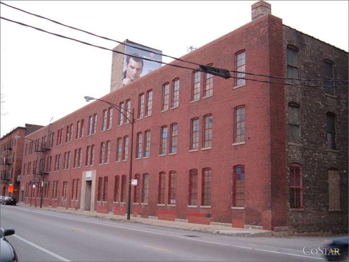
Early Chicago American Flyer Factory Location
So if anyone has any additional thoughts on this odd motor, please let me know. I am planning on taking the motor to future meets to show various friends to get their thoughts.


